4. Electronic prototyping with Arduino#
This week we had to choose a FabLab tool we wanted to learn. The possibilities were :
- Computer controlled cutting
- 3D printing for repair
- Electronic prototyping
I chose the latter.
Introduction to microcontroller#
What is a microcontroller ?#
During these two courses, we learned electronic prototyping using an Arduino microcontroller. Microcontrollers are small relatively cheap computers built on a single integrated circuit. They contain one or more CPUs, memory and programmable input/output peripherals. In contrast to microcomputers, they do not contain any operating system which makes them highly more reactive but restrict them to relatively simple tasks.
The Arduino microcontroller we used is the Ardunio UNO model and looks like this :
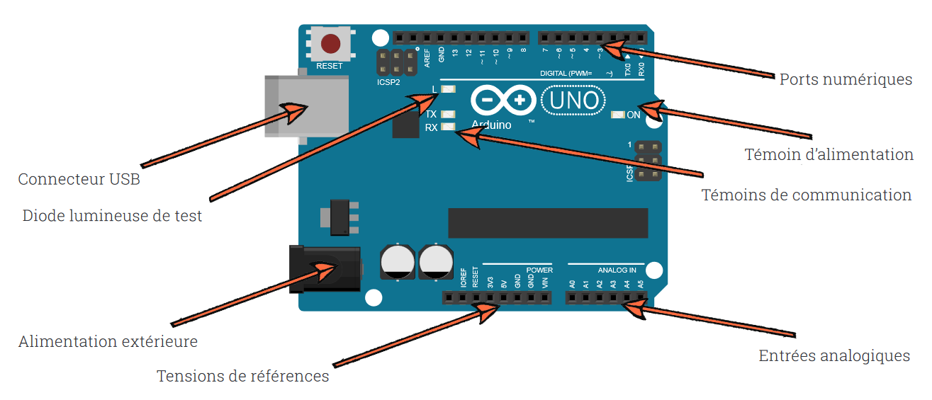
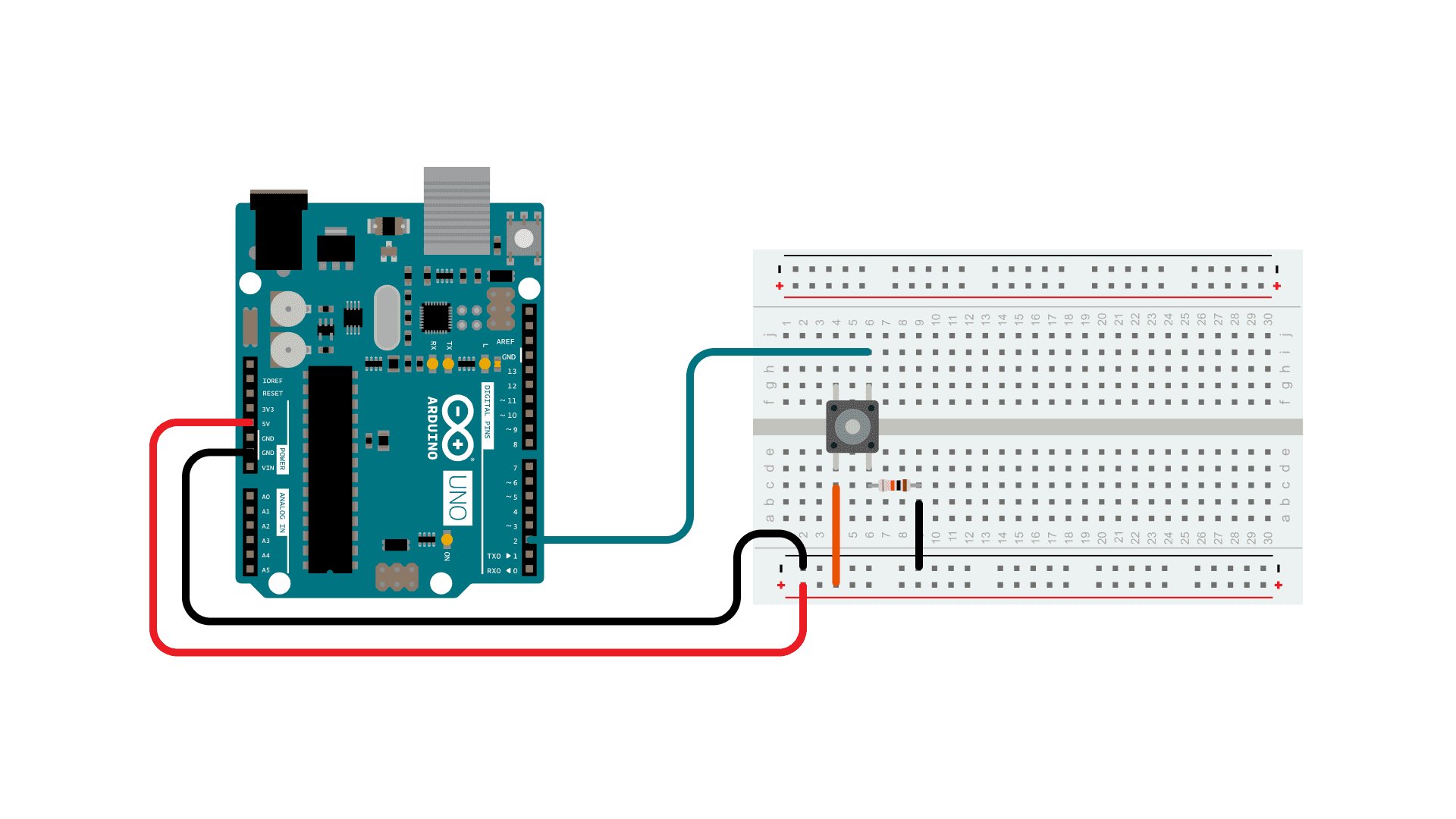
As represented on the picture, the board contains input and output peripherals. In order to plug the input and output devices and to organize them correctly, we used a breadboard. Here is a picture of an RGB led plugged to an Arduino UNO through a breadboard :
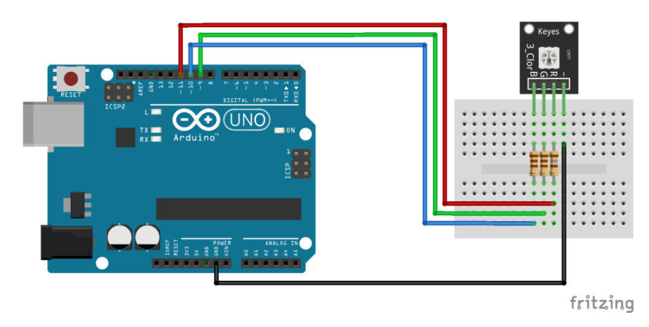
As you can see on this simple example, resitances are plugged on the breadboard between the Arduino and the LED and a black wire is connected to the ground. If you didn’t catch anything from the last sentence, don’t worry. We will do a quick recap of the electrical theory and gently go back to the Arduino.
Electrical theory#
Electrical current and electrical circuit#
Electrical current is the source of energy used in every electrical devices. Physically, it corresponds to the motion of small electrical charges most of the time through wires. More precisely, the current is defined as the amount of charges travelling per second and its unit is called Ampere (A).
In electicity, we use what are called a closed circuits. A closed circuit can be seen as a closed path along which the electrical charges are travelling. At certain points of the path are plugged electrical devices which use the current’s energy as a power source. It is important to understand that the energy source of the devices is not the electrical charges themselves but the energy contained in the latter. The electrical charges can be seen as energy carriers who never go in or out of the circuit as it is closed.
In the specific case of a microcontroller, the current will be travelling in wires from the microcontroller to the breadboard, then in the lines of the bredboard, through the devices we plugged on the latter and come back to the Arduino in a (usually black) wire connected to what is called the ground. All circuits should pass by a ground pin, we will explain why in the next section.
Potential difference and power source#
According to themodynamics principles, energy can not be created or destroyed. Therefore, if we use the electrical current’s energy to power our devices, the current itself must find its energy in another source which is called the potential difference or tension whose units are Volts (V).
To visualise what is a potential difference, imagine the electrical circuit as a river and the electrical current as the river’s flow. In reality the river’s flow is due to the gravity and to the height difference between the beginning and the end of the river : the source is at the top of a moutain, the water is attracted downward and the river ends in the sea. The potential difference between two points of an electrical circuit can be seen as the height difference between two points of a river.
However, in contrast to a river, an electrical circuit is closed. So our imaginary river representing a circuit does not have a source at the top and does not end in the sea. Instead we have to imagine that at the end of the river, there is a pump that continuously brings back the water to the top. The pump conducts back the water from the lowest point of the river to the highest which, in an electrical circuit, is equivalent to the role played by a batery (or any other power source) that brings back the charges to the highest potential in the circuit. As in electrical circuit there is no pre-existing mountain or valley, we also say that, by increasing the charges’ potential, the battery creates the potential difference.
In our case, the power source is the battery of the Arduino itself (or the batery of a computer if the latter is plugged to a computer) which creates a potential difference between its ground pin (where all the circuits end) and an output pin, which is the reason why every circuits should end in the ground pin.
Resistors and Ohm’s law#
In electrical circuit, the current is slowed by resistors which are needed to avoid too high current that could be dangerous for the components. The Ohm’s law allows to compute the current value depending on the potential difference and the resistor’s value :
I = V/R
Before plugging any devices on the Arduino, one should always check the maximum supported values of tension and current of the device to choose the right source pin and the right value of the resistor that has to be plugged between the Arduino on the device on the breadboard.
How to program a microcontroller ?#
Now that we recalled the basics of electrical theory, let’s speak a bit more about the Arduino itself. Fow now, you should wonder what is the interest of a microcontroller since we only talked about it as a tension source but of course the Arduino can do a lot more than a simple battery.
The Arduino board contains a small computer that can start and stop current depending on programmed instructions. For instance, you could write instructions that tell the microcontroller to start a current for 1 second through the output pin number 3 every 10 seconds. If you correctly plugged wires to construct a circuit linking the output pin number 3 to the ground pin and passing through a LED device, you would see a 1 second light flash every 10 seconds.
The interseting thing is that you can also plug input devices and program instructions that depends on the input currents. For example the microcontroller could start a fan plugged on an output pin if the thermometer plugged on an input pin send a signal corresponding to a high temperature.
These instructions can be written and sent to the Arduino board easily using a text editor called Arduino IDE.
Arduino IDE interface#
You can download and install the Arduino IDE here. For this course we downloaded the Legacy IDE version.
If you open Arduino IDE for the first time, you should get a similar window :
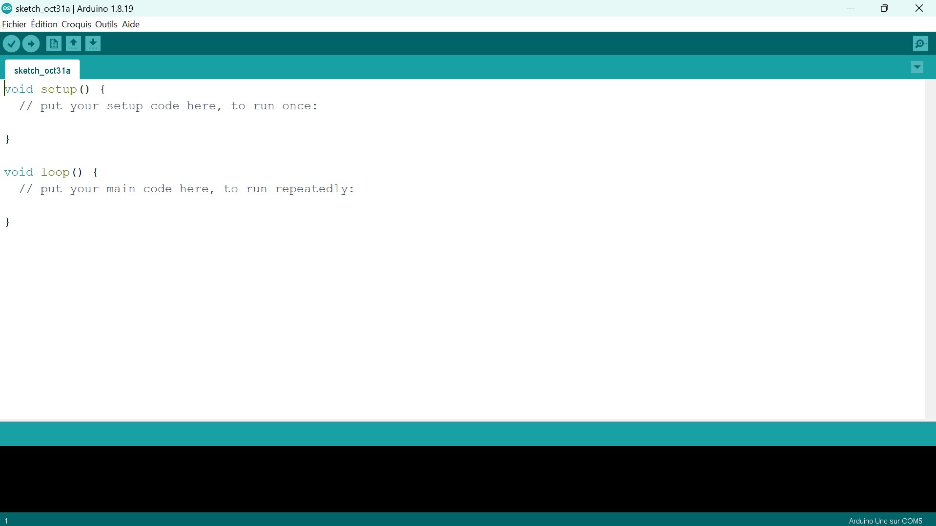
The code in the main window is called the “bare minimum” code :
void setup() {
  // put your setup code here, to run once:

}

void loop() {
  // put your main code here, to run repeatedly:

}
setup() and loop(). The instructions written in the setup() function will be executed by the microcontroller at the moment when he receives the code in its memory. When setup() is done, the instructions written in the loop() function will be repeated until we force it to stop (by sending the microcontroller another code for instance).
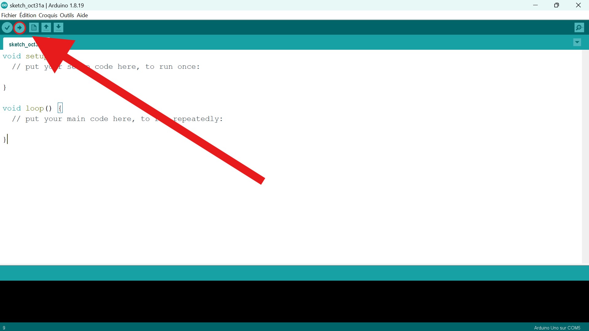
To send your code to the microcontroller, first be sure that it is plugged to your computer, then simply select the Upload button :
Basic example : Button and LED#
Of course, if you send the “bare minimum” to your microcontroller, nothing will happen. During the first course, we were asked to explore the Examples files in order to understand the basic syntax and arduino libraries :
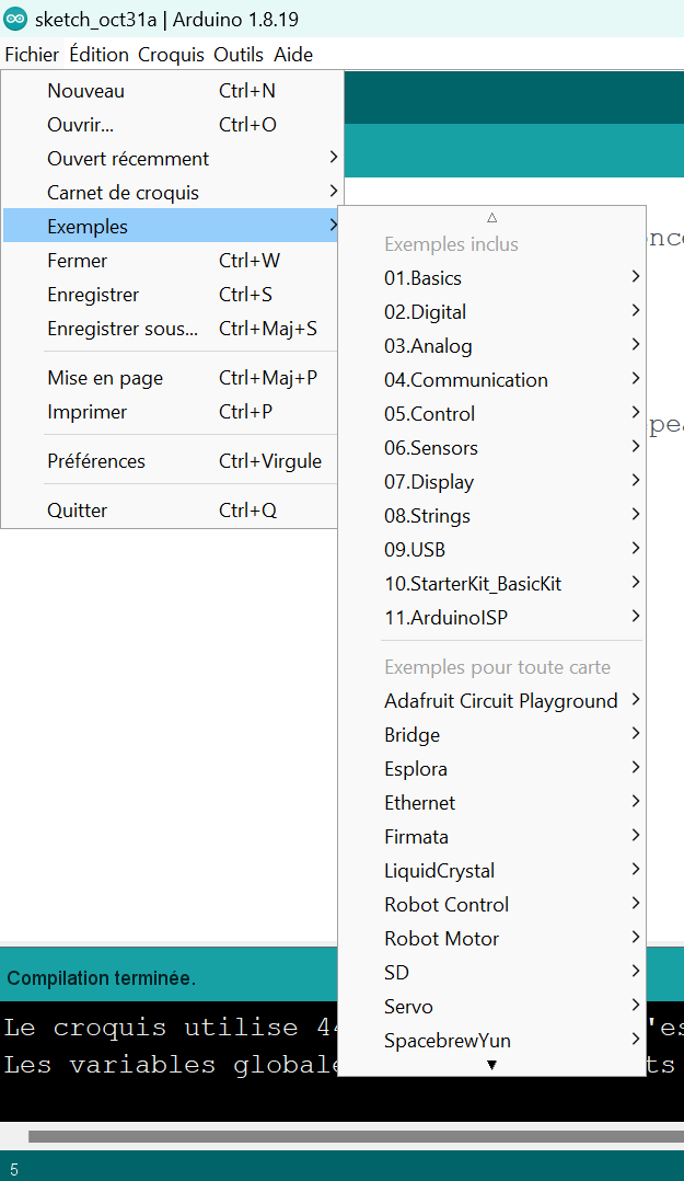
For instance, if you open Files>Examples>Digital>Button, you should see a new window containing the following code :
/*
  Button

  Turns on and off a light emitting diode(LED) connected to digital pin 13,
  when pressing a pushbutton attached to pin 2.

  The circuit:
  - LED attached from pin 13 to ground through 220 ohm resistor
  - pushbutton attached to pin 2 from +5V
  - 10K resistor attached to pin 2 from ground

  - Note: on most Arduinos there is already an LED on the board
    attached to pin 13.

  created 2005
  by DojoDave <http://www.0j0.org>
  modified 30 Aug 2011
  by Tom Igoe

  This example code is in the public domain.

  https://www.arduino.cc/en/Tutorial/BuiltInExamples/Button
*/

// constants won't change. They're used here to set pin numbers:
const int buttonPin = 2;     // the number of the pushbutton pin
const int ledPin =  13;      // the number of the LED pin

// variables will change:
int buttonState = 0;         // variable for reading the pushbutton status

void setup() {
  // initialize the LED pin as an output:
  pinMode(ledPin, OUTPUT);
  // initialize the pushbutton pin as an input:
  pinMode(buttonPin, INPUT);
}

void loop() {
  // read the state of the pushbutton value:
  buttonState = digitalRead(buttonPin);

  // check if the pushbutton is pressed. If it is, the buttonState is HIGH:
  if (buttonState == HIGH) {
    // turn LED on:
    digitalWrite(ledPin, HIGH);
  } else {
    // turn LED off:
    digitalWrite(ledPin, LOW);
  }
}
-
The comment
It is bounded by the
/**/characters. It explains what the code does and how to construct the right circuit in order to make it works. There is also an link ( https://www.arduino.cc/en/Tutorial/BuiltInExamples/Button ) where one can find more detailed explanations on how to construct the circuit and even a picture of it :
-
The variables definitions
These lines are the only uncommented ones not included in a function. They define global variables that will be used often in the functions. This is the place where one should define pin variables. Indeed, if one wants the Arduino to control or read the signal of a device, it should know on which output/input the latter is plugged. Hence, you will use these pin numbers quite often in the code and it is always easier to give them a name. You can see that the pin variables are integers simply containing the number of the pin that is written on the Arduino board.
-
The
setup()This is the place where one actually communicates to the microcontroller which pin is an output or input using the function
pinMode. As mentionned earlier, you can also write code that you want to be executed just once at the moment where the microcontroller receives the instructions. -
The
loop()This is the main part of the code which contains the instructions that will be repeated for the microcontroller to function correctly. Indeed, a computer is not alive and does not “feel” therefore you can not expect it to detect continuously if there is any change around it and to react depending on these changes. Instead, you have to repeateadly give to him the instructions to check if something changed and to react properly. In the example, the “check” instruction is the
digitalReadfunction and the “do something” instruction is thedigitalWritefunction.
DHT projects#
Now that we understand the Arduino basics and Arduino IDE syntax, we can step up a bit our work. The goal of the second course was to connect and use a DHT sensor with the Arduino. A DHT sensor measures the temperature and the humidity rate and send these information to the microcontroller.
How to use a DHT#
IDE librairy setup#
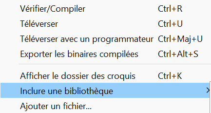
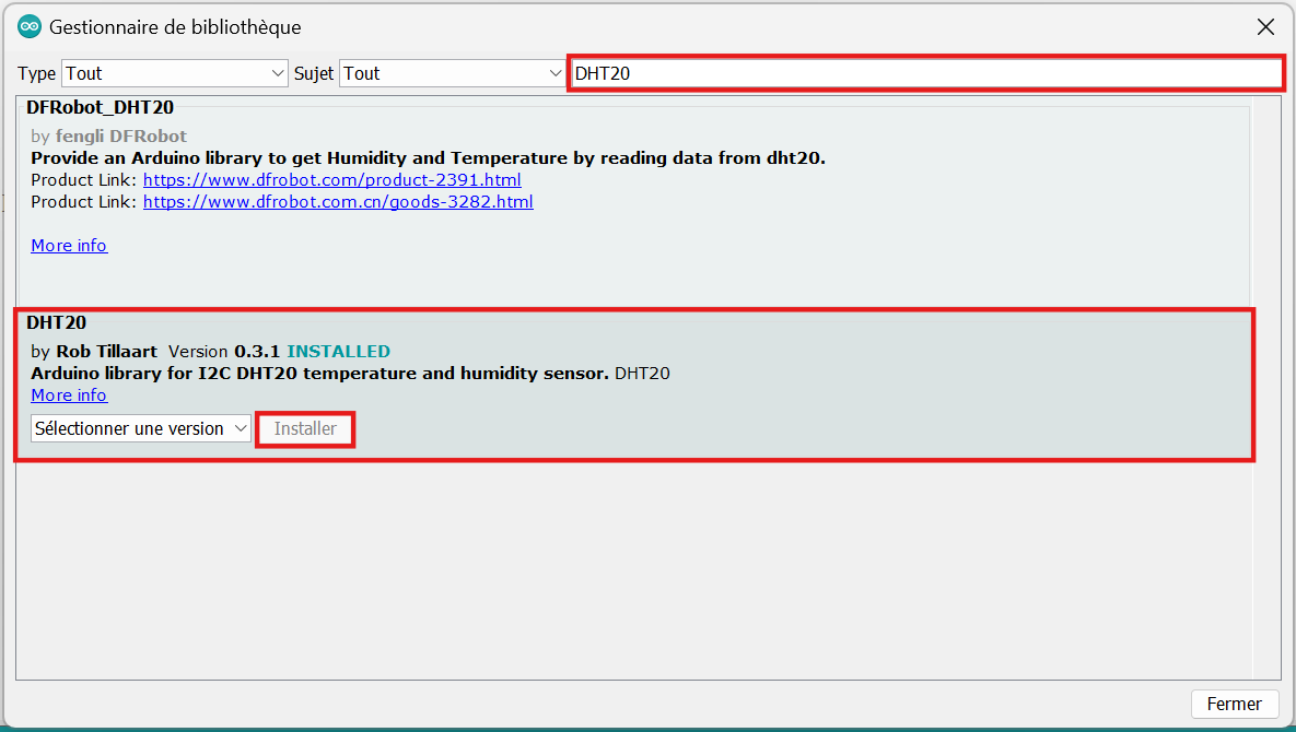
The first step is to install the corresponding librairy on your own Arduino IDE. To do so, select the Sketch menu on the IDE toolbar, then Include a librairy and finally Manage librairies.
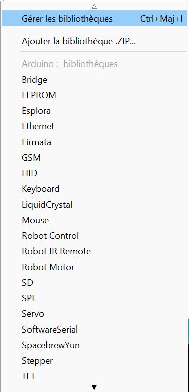
The following window will be displayed, in the search bar, type DHT20 and install the corresponding librairy.
You should now be able to find a DHT20 example in Files>Examples>DHT20>DHT20. The code should be :
//
//    FILE: DHT20.ino
//  AUTHOR: Rob Tillaart
// PURPOSE: Demo for DHT20 I2C humidity & temperature sensor
//     URL: https://github.com/RobTillaart/DHT20
//
//  Always check datasheet - front view
//
//          +--------------+
//  VDD ----| 1            |
//  SDA ----| 2    DHT20   |
//  GND ----| 3            |
//  SCL ----| 4            |
//          +--------------+


#include "DHT20.h"

DHT20 DHT;

uint8_t count = 0;


void setup()
{
  Serial.begin(115200);
  Serial.println(__FILE__);
  Serial.print("DHT20 LIBRARY VERSION: ");
  Serial.println(DHT20_LIB_VERSION);
  Serial.println();

  Wire.begin();
  DHT.begin();    //  ESP32 default pins 21 22


  delay(1000);
}


void loop()
{
  if (millis() - DHT.lastRead() >= 1000)
  {
    //  READ DATA
    uint32_t start = micros();
    int status = DHT.read();
    uint32_t stop = micros();

    if ((count % 10) == 0)
    {
      count = 0;
      Serial.println();
      Serial.println("Type\tHumidity (%)\tTemp (°C)\tTime (µs)\tStatus");
    }
    count++;

    Serial.print("DHT20 \t");
    //  DISPLAY DATA, sensor has only one decimal.
    Serial.print(DHT.getHumidity(), 1);
    Serial.print("\t\t");
    Serial.print(DHT.getTemperature(), 1);
    Serial.print("\t\t");
    Serial.print(stop - start);
    Serial.print("\t\t");
    switch (status)
    {
      case DHT20_OK:
        Serial.print("OK");
        break;
      case DHT20_ERROR_CHECKSUM:
        Serial.print("Checksum error");
        break;
      case DHT20_ERROR_CONNECT:
        Serial.print("Connect error");
        break;
      case DHT20_MISSING_BYTES:
        Serial.print("Missing bytes");
        break;
      case DHT20_ERROR_BYTES_ALL_ZERO:
        Serial.print("All bytes read zero");
        break;
      case DHT20_ERROR_READ_TIMEOUT:
        Serial.print("Read time out");
        break;
      case DHT20_ERROR_LASTREAD:
        Serial.print("Error read too fast");
        break;
      default:
        Serial.print("Unknown error");
        break;
    }
    Serial.print("\n");
  }
}


//  -- END OF FILE --
You can see that, in contrast to the Arduino documentation’s examples, there is no link leading to a explanation or a picture of the circuit to indicate us how to plug the DHT. This will mainly be the case when you have to use a new device with a microcontroller. We will have to look the device documentation by ourselves.
Plugging setup#
To find your device documentation, try to find the brand and model of your device. I am working wiht a DHT20 from ASAIR, then by looking for “DHT20 ASAIR data sheet”, I can find the required data sheet.
On the data sheet you can find a lot of informations. The ones we will use are :
-
The sensor specifications
-
The expansion performance
-
The interface definition
-
The electrical characteristics
For now, let us have a look to the interface definition section. We can find the following pictures explaining what are each pins.
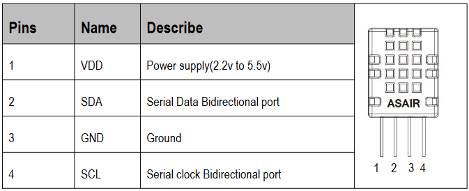
We can easily understand that the first one is where we should plug the tension source and the third one where we should plug the ground pin. The SDA is indicated to be the pin from which the data (temperature and humidity measures) will travel to the microcontroller and the SCL is used to synchronize the microcontroller with the sensor. It is not important here to understand how they work but it is important to know they have to be linked respectively with SDA and SCL pins on the Arduino board.
We are now almost ready to plug the sensor. However, we still need to check what are the electrical characteristics to find if there are maximum supported values of tension or current. You can find the following table.
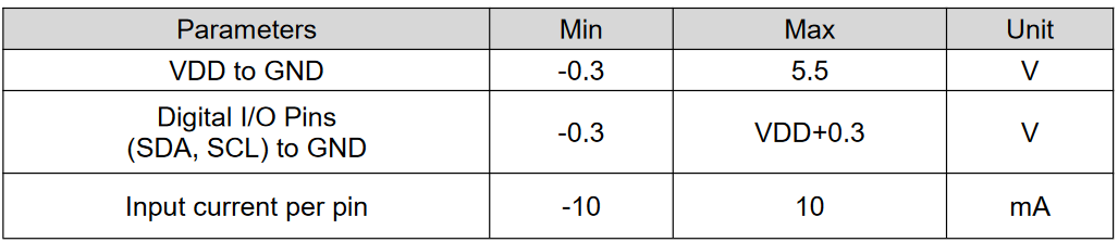
The important point here is to notice that the maximum tension we can plug on the VDD pin is 5.5 Volts (hopefully the maximum tension source on the Arduino board is 5 Volts) and that the SDA and SCL pins can not support more than the VDD tension + 0.3 Volts. Therefore we can note plug the VDD pin on the 3 Volts tension source on the Arduino since the SDA and SCL signal are linked to the microcontroller whose inner tension is 5 Volts. This leaves only one possibility : plug the VDD pin on the 5 Volts pin of the Arduino board.
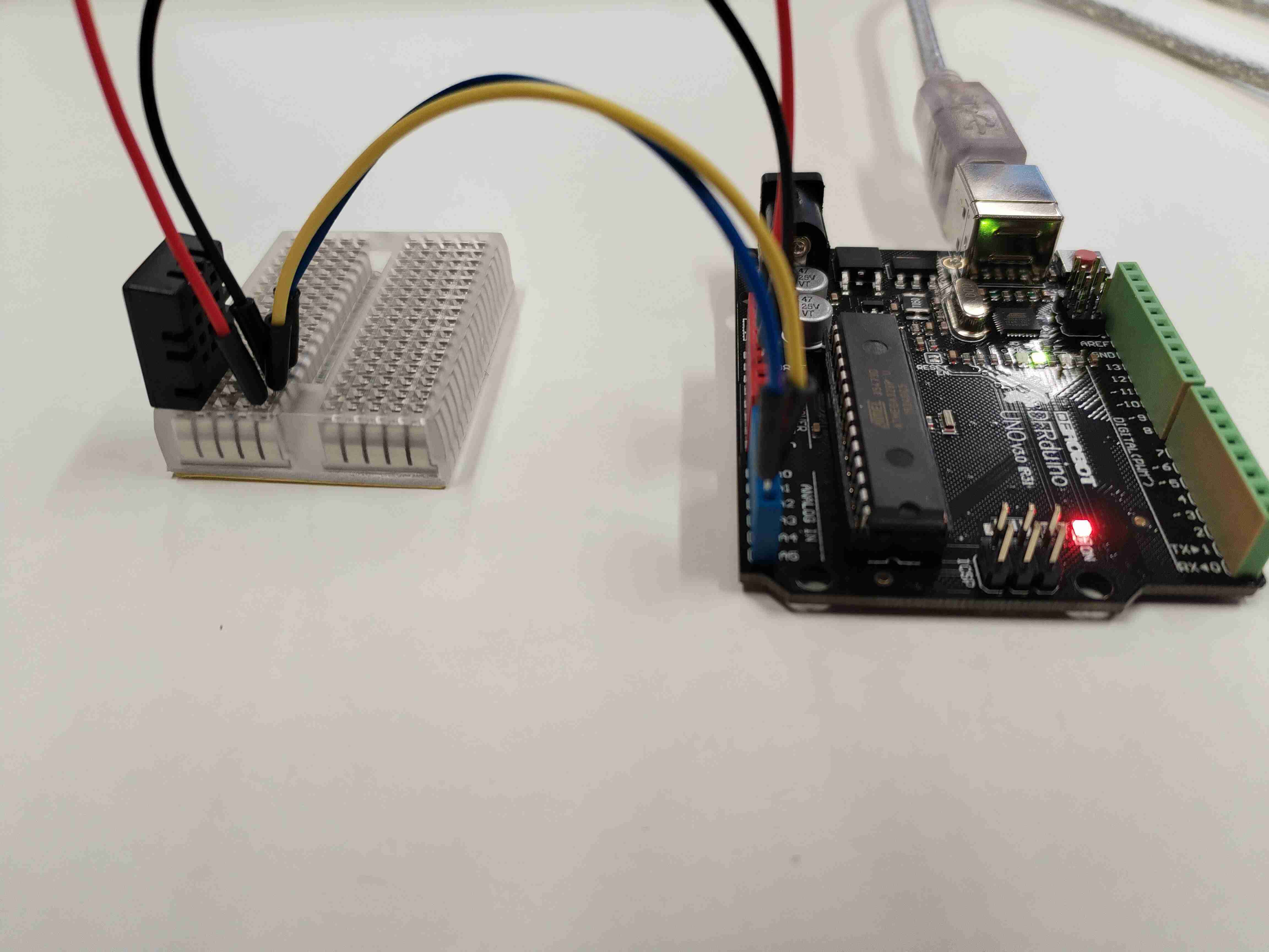
The ground must obvisouly be connected to the groud pin and as mentionned before SDA and SCL pins of the sensor should be plugged to their analogs on the Arduino board. If the SDA and SCL pins of your board are not directly indicated on the latter, look for the “pinouts doc” of your board. You should find something similar to :
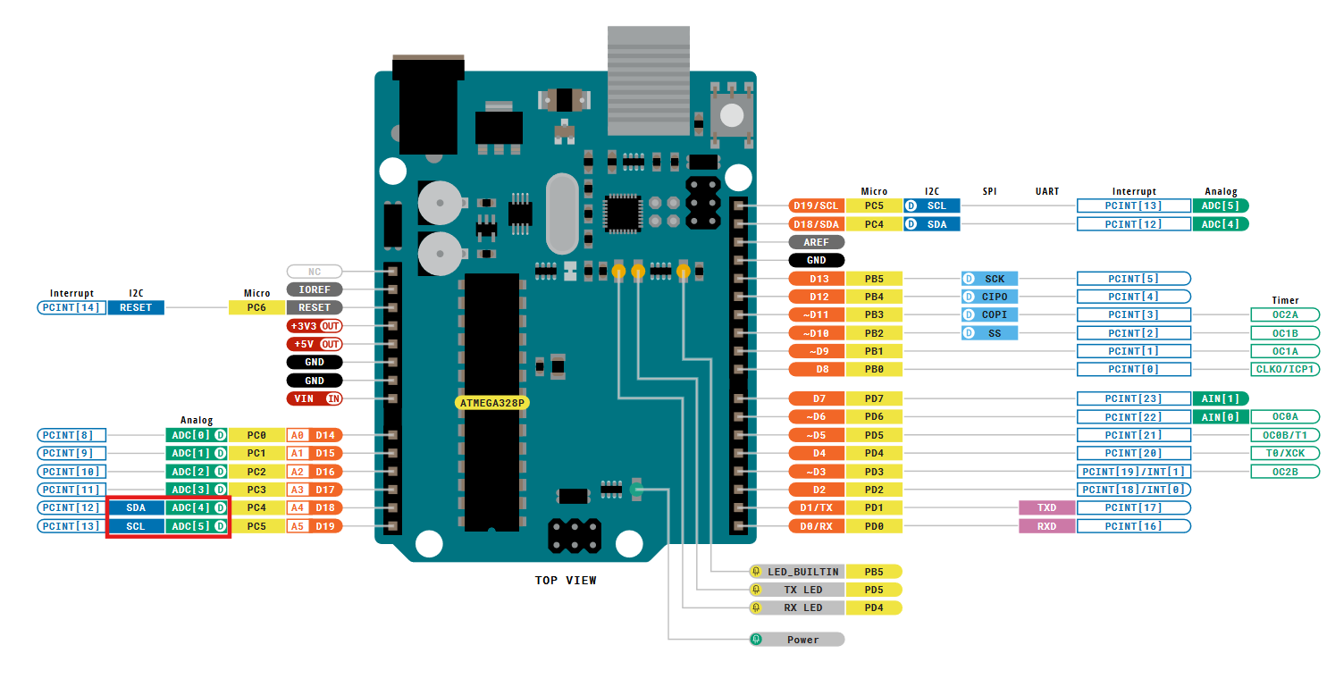
where I highlighted in red the SDA and SCL pins. Hence I know SDA pin is indicated A4 on the board and SCL is indicated A5.
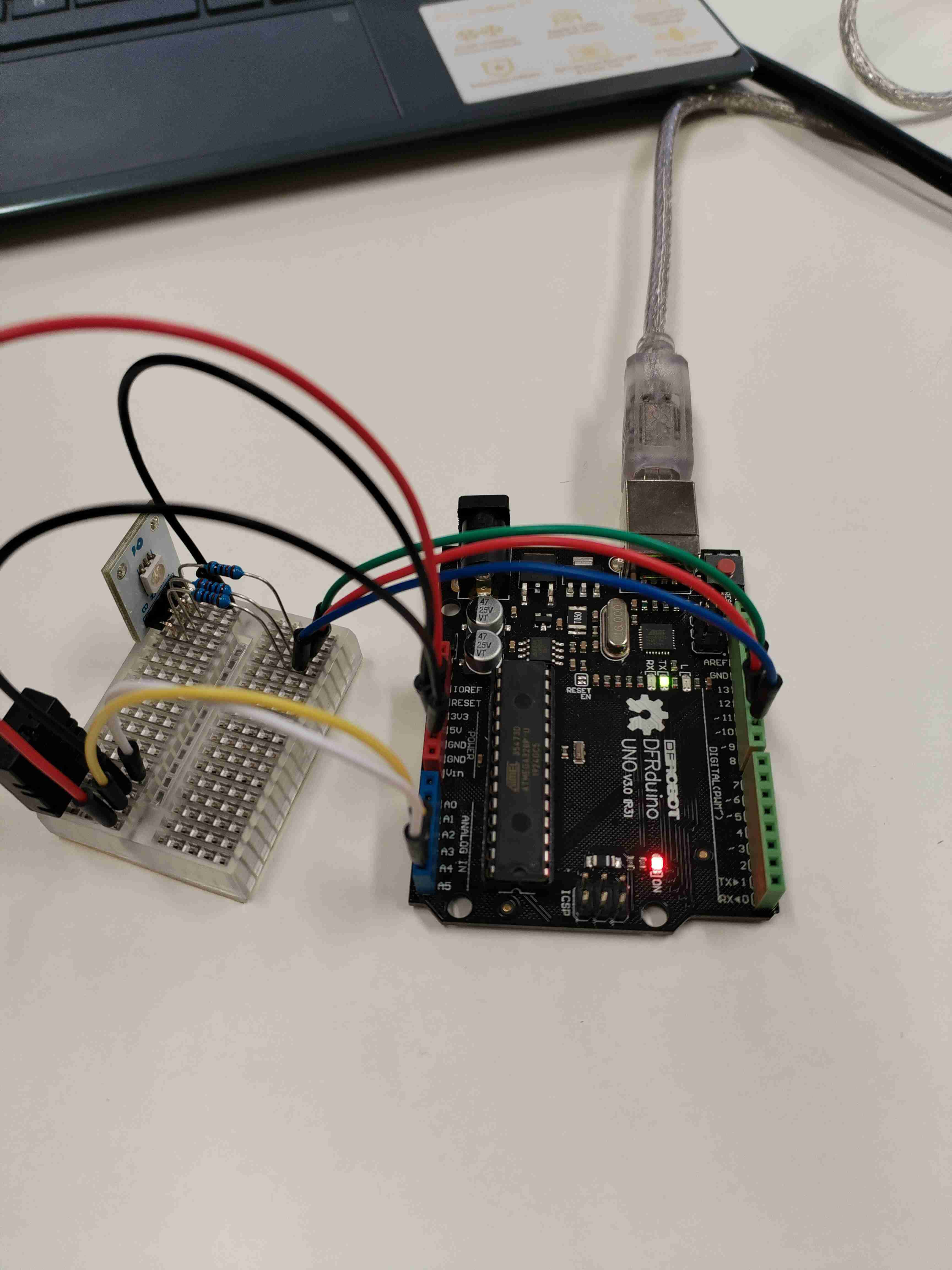
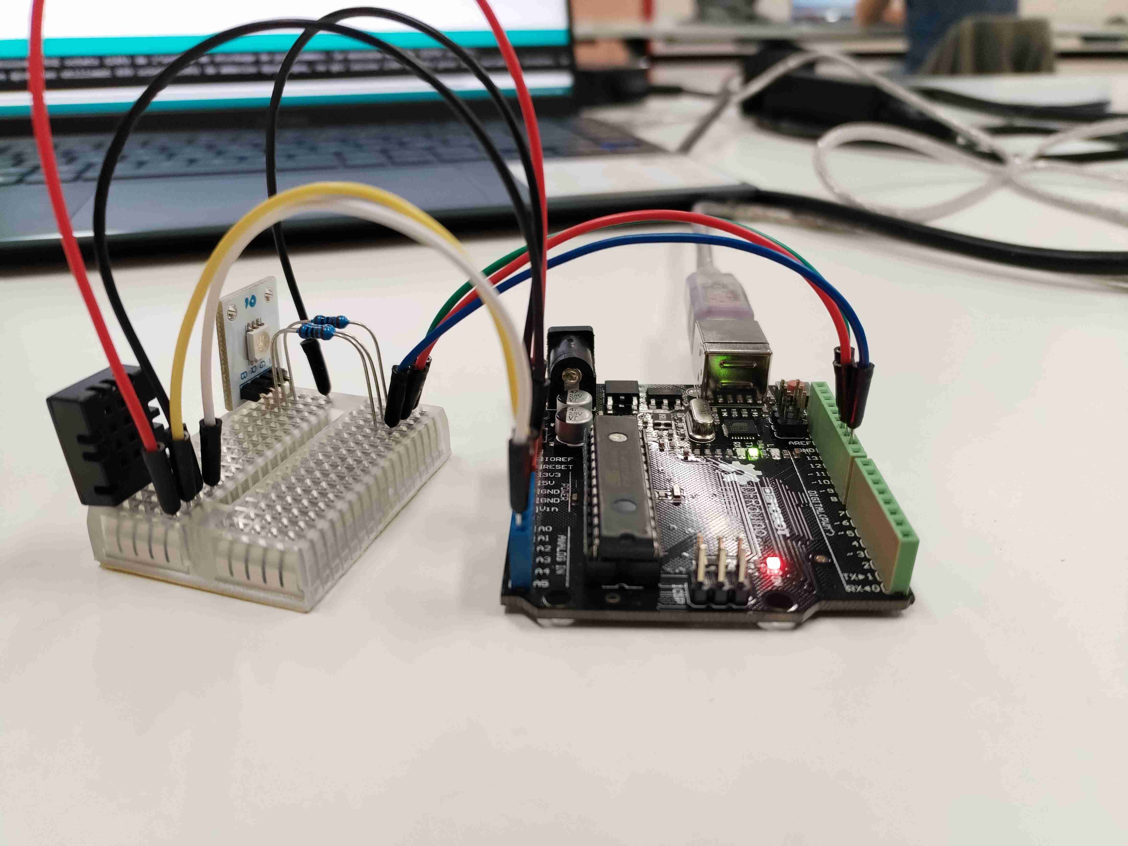
We can now plug everything and get :
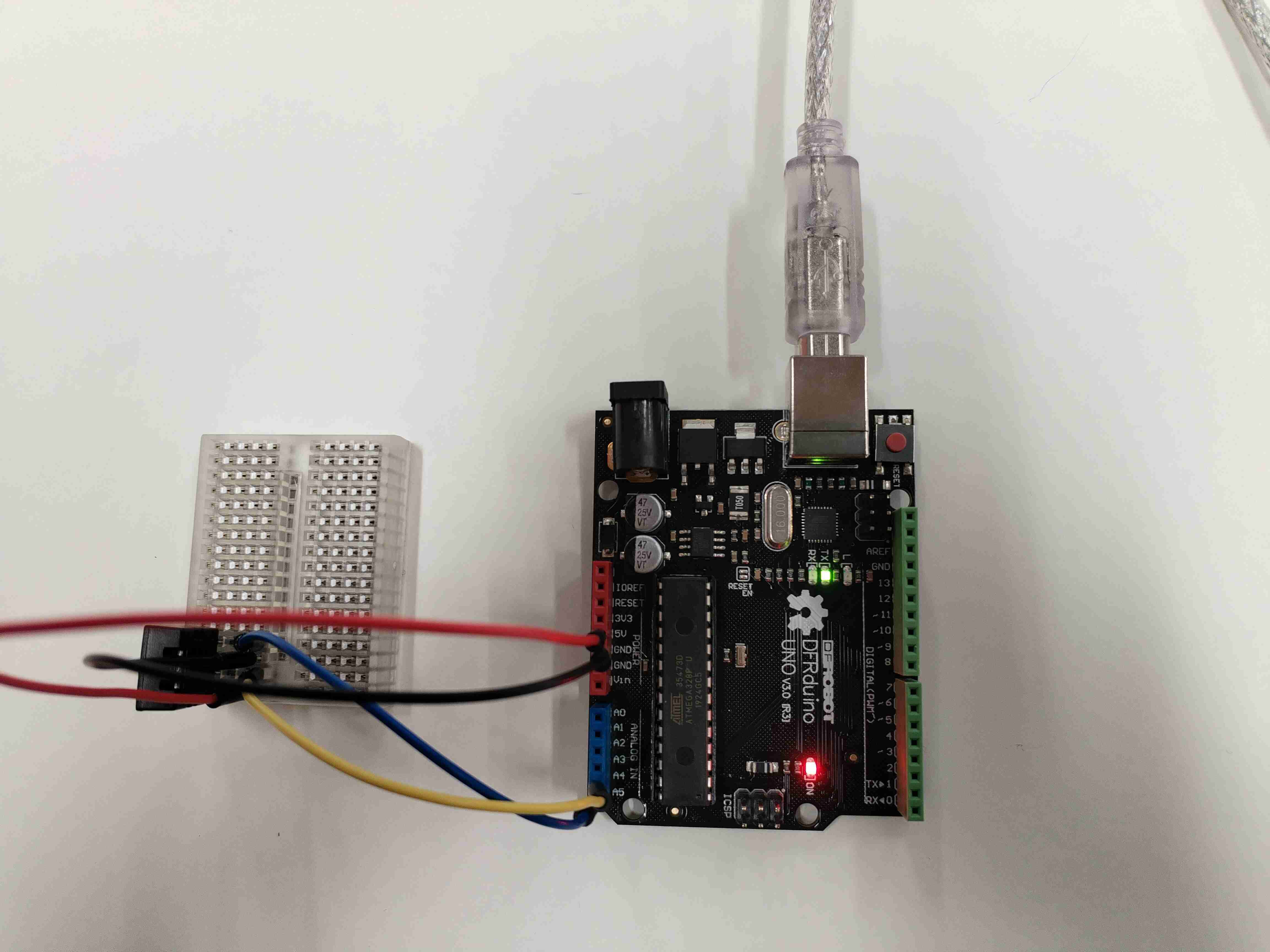
We are now ready to read the data measured by the sensor ! Let’s get back on the IDE.
How to display the DHT data#
If everything is correctly plugged (be sure that your Arduino board is connected to your computer…), you can open the DHT20 example in the Arduino IDE. Then, upload the code to the microcontroller.
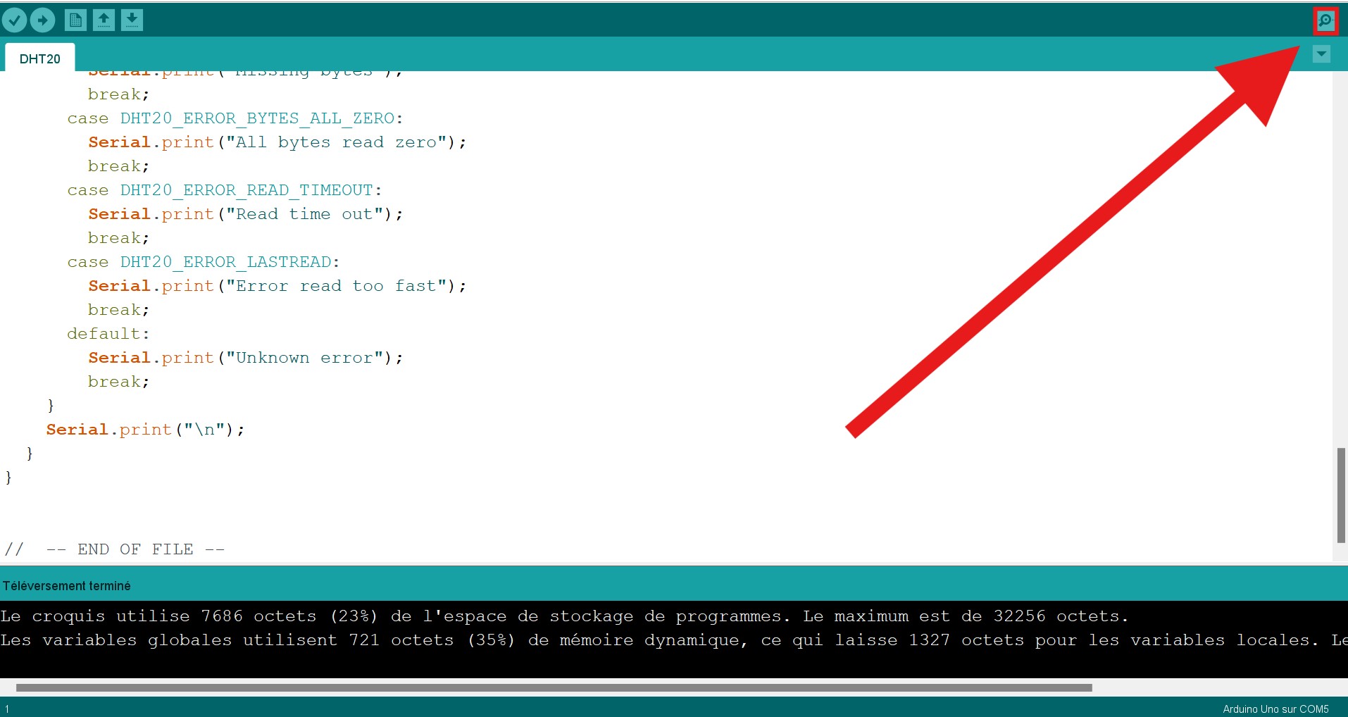
Wait a few seconds for the uploading process to be done and then select the small button on the top-right corner of the IDE.
The following window should appear, and congrats ! You should be able to read the data measured by the sensor !
Well… maybe not yet…
If, like me, you get some measurements correctly and then nothing else than the following weird symbols, don’t worry, it is easily fixable. Check the number on the bottom-right corner of the window. It indicates the “speed rate” at which the microcontroller reads the data he receives from the sensor.
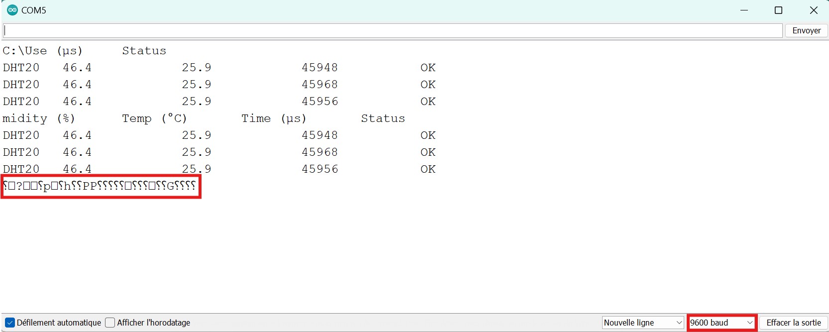
Well, that number has to be equal to the “speed rate” at which the sensor sends the data otherwise their will be a problem when the microcontroller translates the analog signal into readable characters. And… we did not verify if the sending speed rate of the sensor was actually the same.
Close the window to go back to the code and check the setup() function. Change the Serial.begin() argument to the same speed rate as the one at which the microcontroller reads.
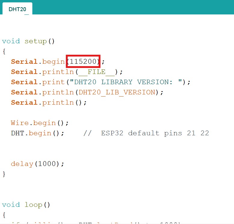
Reupload the code on the microcontroller, and now, you should finally get understandable measurements !
We can read the numbers correctly but wouldn’t a graph be easier to read ?
I agree and it’s easy to do ! In the DHT20 examples librairy, load the DHT20_plotter. You should get the following code.
//
//    FILE: DHT20_plotter.ino
//  AUTHOR: Rob Tillaart
// PURPOSE: Demo for DHT20 I2C humidity & temperature sensor
//     URL: https://github.com/RobTillaart/DHT20
//
//  Always check datasheet - front view
//
//          +--------------+
//  VDD ----| 1            |
//  SDA ----| 2    DHT20   |
//  GND ----| 3            |
//  SCL ----| 4            |
//          +--------------+


#include "DHT20.h"

DHT20 DHT(&Wire);


void setup()
{
  Wire.begin();
  DHT.begin();  //  ESP32 default pins 21 22

  Serial.begin(115200);
  Serial.println("Humidity, Temperature");
}


void loop()
{
  if (millis() - DHT.lastRead() >= 1000)
  {
    //  note no error checking
    DHT.read();
    Serial.print(DHT.getHumidity(), 1);
    Serial.print(", ");
    Serial.println(DHT.getTemperature(), 1);
  }
}


//  -- END OF FILE --
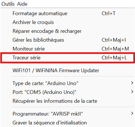
Be sure to modify the Serial.begin() argument once more and then upload the code on your microcontroller. When it’s done select Tools>Serial tracer.
You should then get a beautiful live graph tracer of the data measured by the sensor.
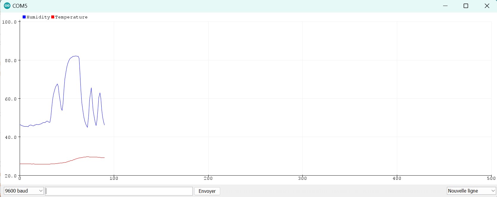
On the graph above, you can see three small blue peaks and a larger and higher one. You can also see that the temperature is increasing only at the beginning of the large blue peak.
The three small blue peaks were produced by blowing on the sensor. Indeed blowed air from your mouth is quite humid. However, as it is blowed, it goes away too fast to increase the temperature measured by the sensor.
The large peak was produced by someone putting his finger on the sensor. His finger’s humidity and temperature then increased the measured data.
Humidity Threshold#
The second assignement for this module was to use the DHT sensor and one or more output devices that would react to the data sent by the sensor. The first idea I had was to plug a led that would light up when the humidity rate overcome a fixed threshold.
The led I had was the Velleman VMA318 whose data sheet can be found here. A plugging scheme can be found directly on the data sheet :
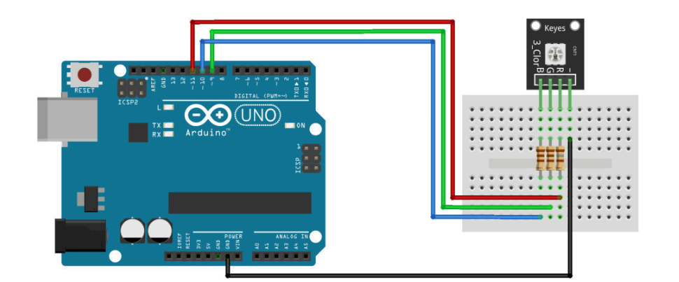
The important thing to notice is that the currents going in the RGB led have to limited by resistors. The maximal supported continuous current’s intensity is 25 mA and the microcontroller inner tension is 5 Volts hence the resistors have to be at least 200 Ohms.
Using these informations I added the RGB led to my breadboard with 1kOhms resistors and I got what’s represented on the following picture.
To program the threshold idea, I simply copied the DHT20 original code and added few lines to control the light.
First of all, in the global variables definition part, I defined pin variables for each light of the RGB led :
and of course in thesetup() function, I defined these pin as outputs :
void setup()
{

  [...]

  pinMode(redPin, OUTPUT);
  pinMode(bluePin, OUTPUT);
  pinMode(greenPin, OUTPUT);
}
loop() function, I control the light by turning it up when the humidity overcomes the threshold and turning it off when the humidity is lower than the threshold :
void loop()
{

    [...]

    if (DHT.getHumidity() > 50.0){
      digitalWrite(redPin,1);
    }
    else{
      digitalWrite(redPin, 0);
    }

    [...]

}
`
Humidity Threshold Alarm#
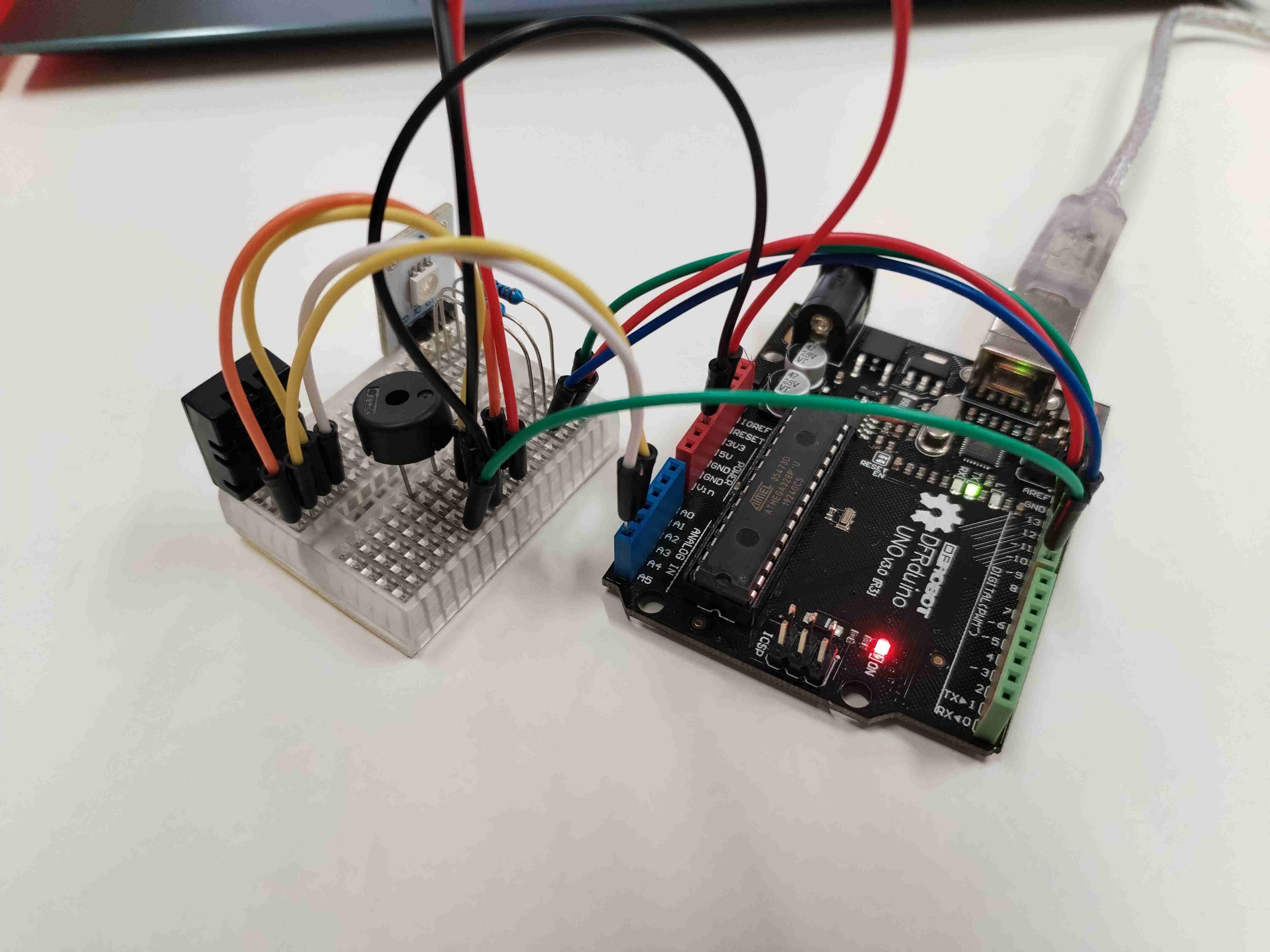
The last thing I wanted to do was to add a speaker tat would sounds like an alarm when the humidity threshold is overcomed. Also, I modified a bit the led code so it would light up like a blue and red rotating beacon when the alarm turns on.
The speaker data sheet can be found here (I used the PS1240P02BT model). No plugging scheme can be found there but it is quite easy to plug. One branch has to be linked to an output pin of the Arduino board that would send a signal when the threshold is overcomed and the other branch has to be linked to the Arduino’s ground pin.
To program the alarm idea, I copied the previous code and added few lines to control the sound and the rotating beamer effect.
In order to control the sound device, I mainly copied few lines of Examples>Digital>toneMelody.
First of all, in the global variables definition part, we need to define melody[] and noteDurations[] lists to respectively customize the notes and tempo of the sound. A lightState variable is also usefull to controll the red/blue alternance :
// notes in the melody:
int melody[] = {
  NOTE_C4, NOTE_G3, NOTE_C4, NOTE_G3, NOTE_C4, NOTE_C4, NOTE_G3, NOTE_G3
};

// note durations: 4 = quarter note, 8 = eighth note, etc.:
int noteDurations[] = {
  4, 4, 4, 4, 4, 4, 4, 4
};

int lightState = 0;
melody[] elements are defined as int but seems to be strings. Actually, the script includes a pitch.h file at the beginning :
which contains the following lines defining some public constants:
/*************************************************
   Public Constants
 *************************************************/

#define NOTE_B0  31
#define NOTE_C1  33
#define NOTE_CS1 35
#define NOTE_D1  37
#define NOTE_DS1 39
#define NOTE_E1  41
#define NOTE_F1  44
#define NOTE_FS1 46
#define NOTE_G1  49
#define NOTE_GS1 52
#define NOTE_A1  55
#define NOTE_AS1 58
#define NOTE_B1  62
#define NOTE_C2  65
#define NOTE_CS2 69
#define NOTE_D2  73
#define NOTE_DS2 78
#define NOTE_E2  82
#define NOTE_F2  87
#define NOTE_FS2 93
#define NOTE_G2  98
#define NOTE_GS2 104
#define NOTE_A2  110
#define NOTE_AS2 117
#define NOTE_B2  123
#define NOTE_C3  131
#define NOTE_CS3 139
#define NOTE_D3  147
#define NOTE_DS3 156
#define NOTE_E3  165
#define NOTE_F3  175
#define NOTE_FS3 185
#define NOTE_G3  196
#define NOTE_GS3 208
#define NOTE_A3  220
#define NOTE_AS3 233
#define NOTE_B3  247
#define NOTE_C4  262
#define NOTE_CS4 277
#define NOTE_D4  294
#define NOTE_DS4 311
#define NOTE_E4  330
#define NOTE_F4  349
#define NOTE_FS4 370
#define NOTE_G4  392
#define NOTE_GS4 415
#define NOTE_A4  440
#define NOTE_AS4 466
#define NOTE_B4  494
#define NOTE_C5  523
#define NOTE_CS5 554
#define NOTE_D5  587
#define NOTE_DS5 622
#define NOTE_E5  659
#define NOTE_F5  698
#define NOTE_FS5 740
#define NOTE_G5  784
#define NOTE_GS5 831
#define NOTE_A5  880
#define NOTE_AS5 932
#define NOTE_B5  988
#define NOTE_C6  1047
#define NOTE_CS6 1109
#define NOTE_D6  1175
#define NOTE_DS6 1245
#define NOTE_E6  1319
#define NOTE_F6  1397
#define NOTE_FS6 1480
#define NOTE_G6  1568
#define NOTE_GS6 1661
#define NOTE_A6  1760
#define NOTE_AS6 1865
#define NOTE_B6  1976
#define NOTE_C7  2093
#define NOTE_CS7 2217
#define NOTE_D7  2349
#define NOTE_DS7 2489
#define NOTE_E7  2637
#define NOTE_F7  2794
#define NOTE_FS7 2960
#define NOTE_G7  3136
#define NOTE_GS7 3322
#define NOTE_A7  3520
#define NOTE_AS7 3729
#define NOTE_B7  3951
#define NOTE_C8  4186
#define NOTE_CS8 4435
#define NOTE_D8  4699
#define NOTE_DS8 4978
noteDuration[] list is not really usefull but it is intersting to see that it can be really easily modified.
Then, the if(DHT.getHumidity() > 50.0) bloc in the loop() function needs to be completely rewritten as :
void loop()
{

    [...]

    if (DHT.getHumidity() > 50.0){
      for (int thisNote = 0; thisNote < 8; thisNote++) {
        lightState = thisNote%2;
        digitalWrite(redPin, lightState);
        digitalWrite(bluePin, 1-lightState);

        // to calculate the note duration, take one second divided by the note type.
        //e.g. quarter note = 1000 / 4, eighth note = 1000/8, etc.
        int noteDuration = 1000 / noteDurations[thisNote];
        tone(8, melody[thisNote], noteDuration);

        // to distinguish the notes, set a minimum time between them.
        // the note's duration + 30% seems to work well:
        int pauseBetweenNotes = noteDuration * 1.30;
        delay(pauseBetweenNotes);
        // stop the tone playing:
        noTone(8);
      }
    }
    else{
      digitalWrite(redPin, 0);
      digitalWrite(bluePin, 0);
    }

    [...]

}
for loop allows to travel through the melody list.
At each iteration it is needed to alternate the light colour :
and to emit a sound corresponding to the note of themelody list and to do a break before the next notes is played :
// to calculate the note duration, take one second divided by the note type.
//e.g. quarter note = 1000 / 4, eighth note = 1000/8, etc.
int noteDuration = 1000 / noteDurations[thisNote];
tone(8, melody[thisNote], noteDuration);

// to distinguish the notes, set a minimum time between them.
// the note's duration + 30% seems to work well:
int pauseBetweenNotes = noteDuration * 1.30;
delay(pauseBetweenNotes);
// stop the tone playing:
noTone(8);
tone() function. Same thing for the noTone() function to stop the sound.
The result can be seen in the following video :
`