3. 3D Printing with Prusa#
During the fourth week, we learned how to use the Prusa 3D printers at the FabLab. We had to print the models we designed the week before.
The ULB FabLab owns Prusa i3 MK3S/S+ printers :
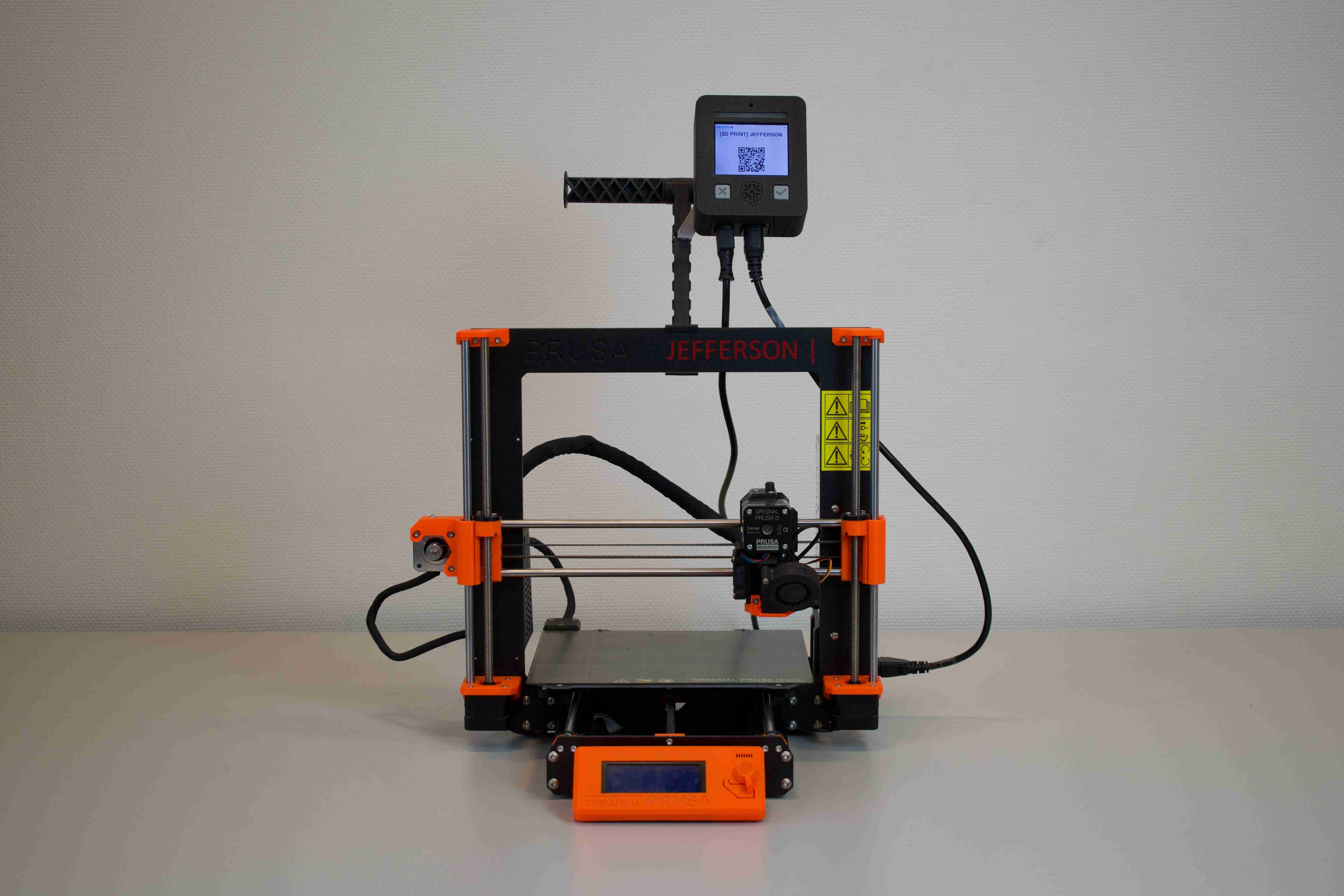
They come with a slicer software called PrusaSlicer whose goal is to convert a 3D model file (.stl, .obj or .3mf) into a code, called G-code, that the printer can understand.
Before opening PrusaSlicer…#
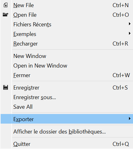
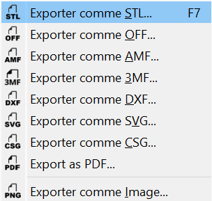
You maybe noticed that the model file formats I cited above does not contain the OpenSCAD file format .scad. Indeed, you need to export your OpenSCAD project to one of the format above (.stl, .obj or .3mf) in order to import you model in PrusaSlicer. Fortunately OpenSCAD allows one to export easily. Open your desired model in OpenSCAD, go to Files-Export-Export as STL and voilà !
PrusaSlicer#
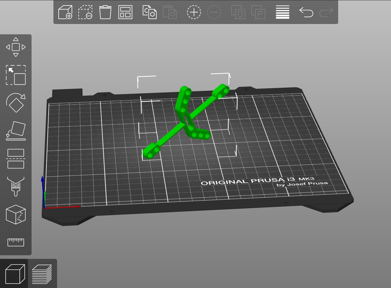
Once you have a 3D model in a format supported by PrusaSlicer, you can open the software. You should see a similar window :
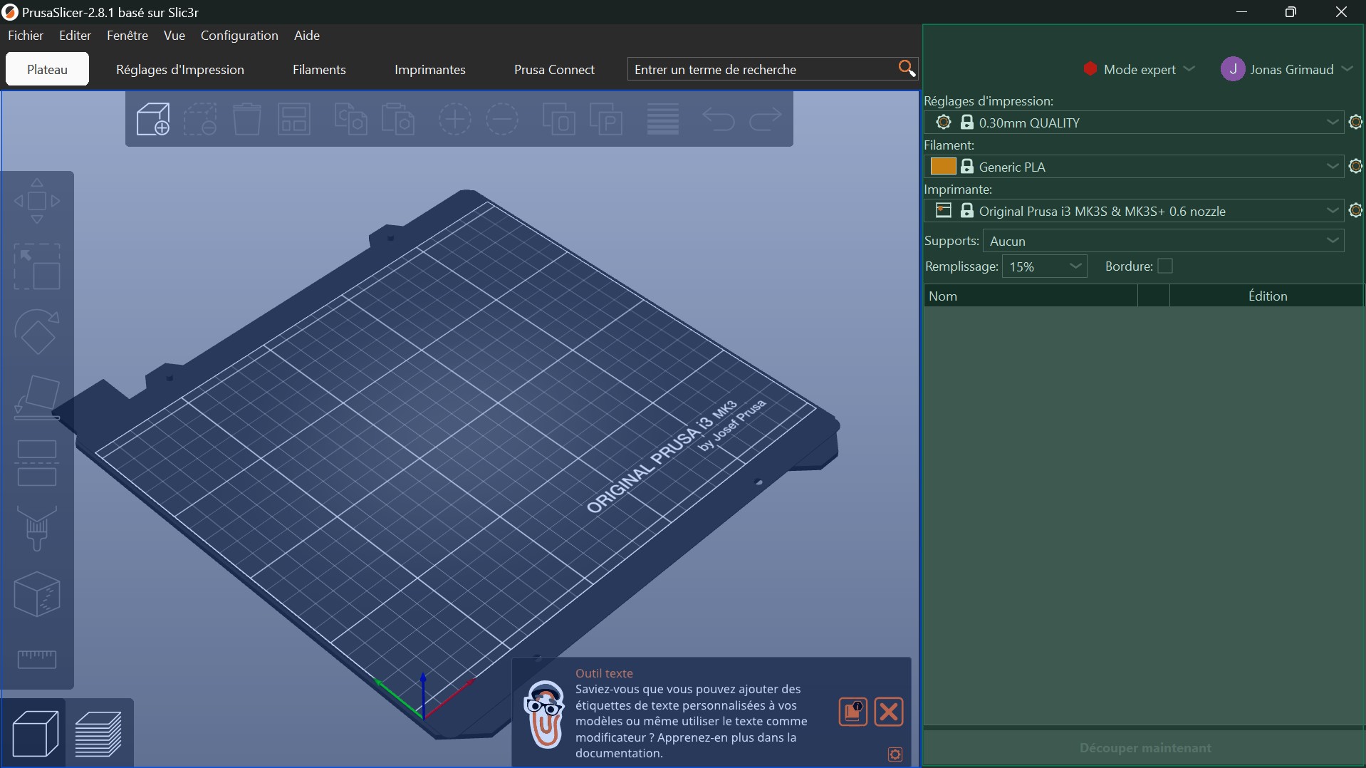
The blue highlighted part is the placement window and allows to modify the orientation and placement of your model on the printing board. The green-highlighted part is the printing configuration window and allows you to modify the printing settings.
Notice that at the top of the green window, the Expert mode is selected, do the same.
Placement#
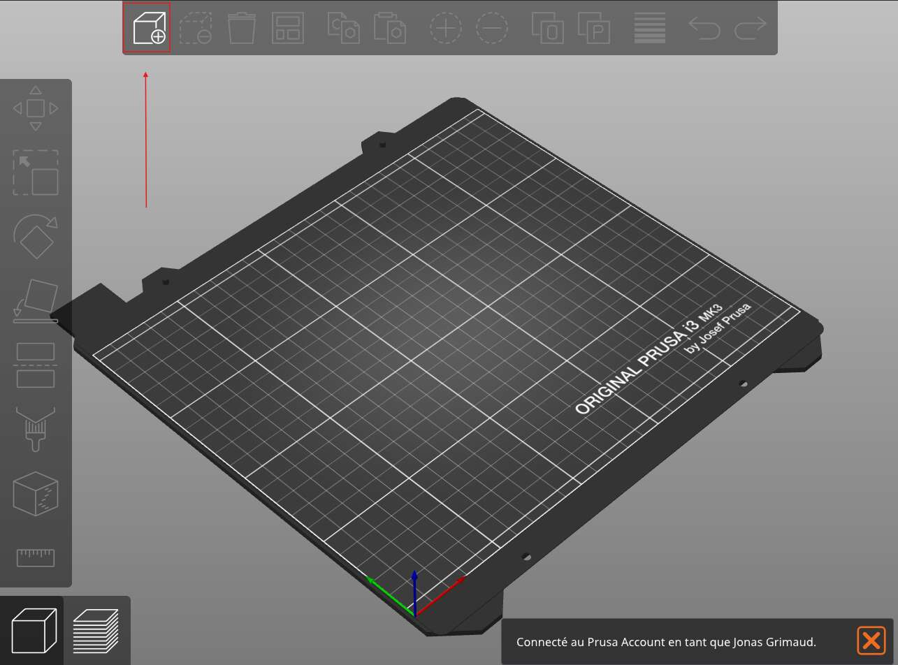
In the placement window, import your 3D model by selecting the Import logo :
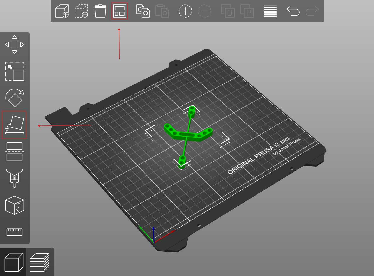
Once your model is imported you have to place it in a ideal position for the printing process. The largest surface of the model should be facing to the floor. PrusaSlicer places your model in such a position if you select the Place logo. If you imported more than one model, you can also arrange them by selecting Arange.
Slicing configuration#
Let’s now have a look at the printing settings, we will use the following ones :
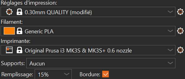
- The first setting defines the printing layer’s height. It defines the vertical resolution of the printing process, 0.3 mm coressponds to the medium quality resolution and it is precise enough for what we want to do.
- The second one is the material you will use to print.
- The third one is the 3D printer model you use.
We will discuss about the last ones a bit later. For now just press Cut Now at the bottom of the printing settings window :
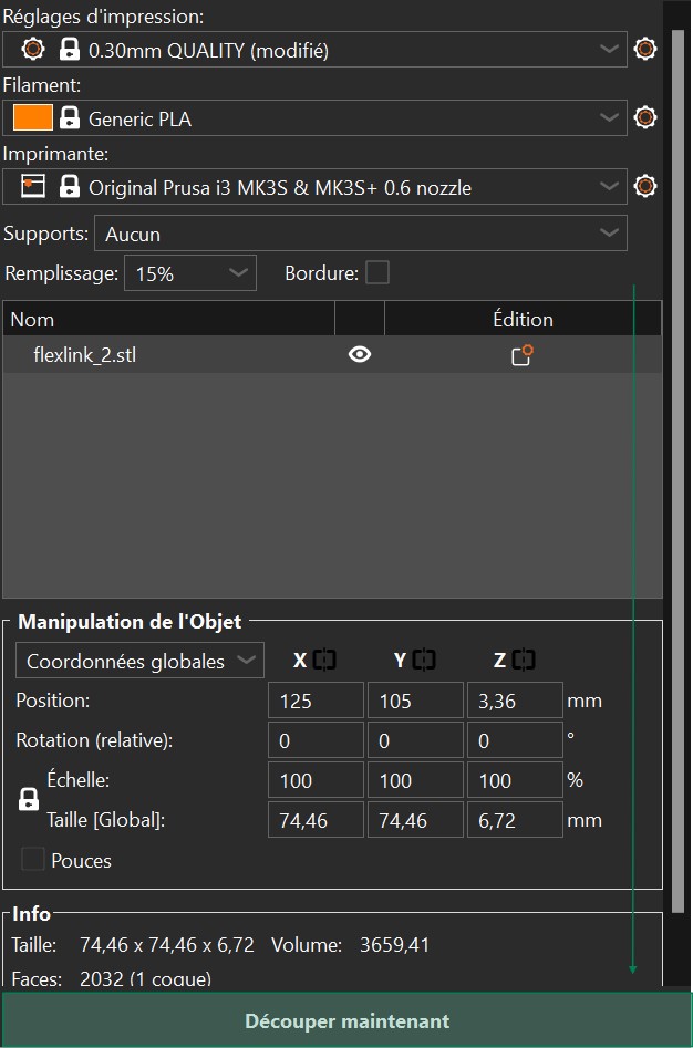
The placement window is now a cut preview window. You can switch between placement and cut preview by using the bottom left buttons.
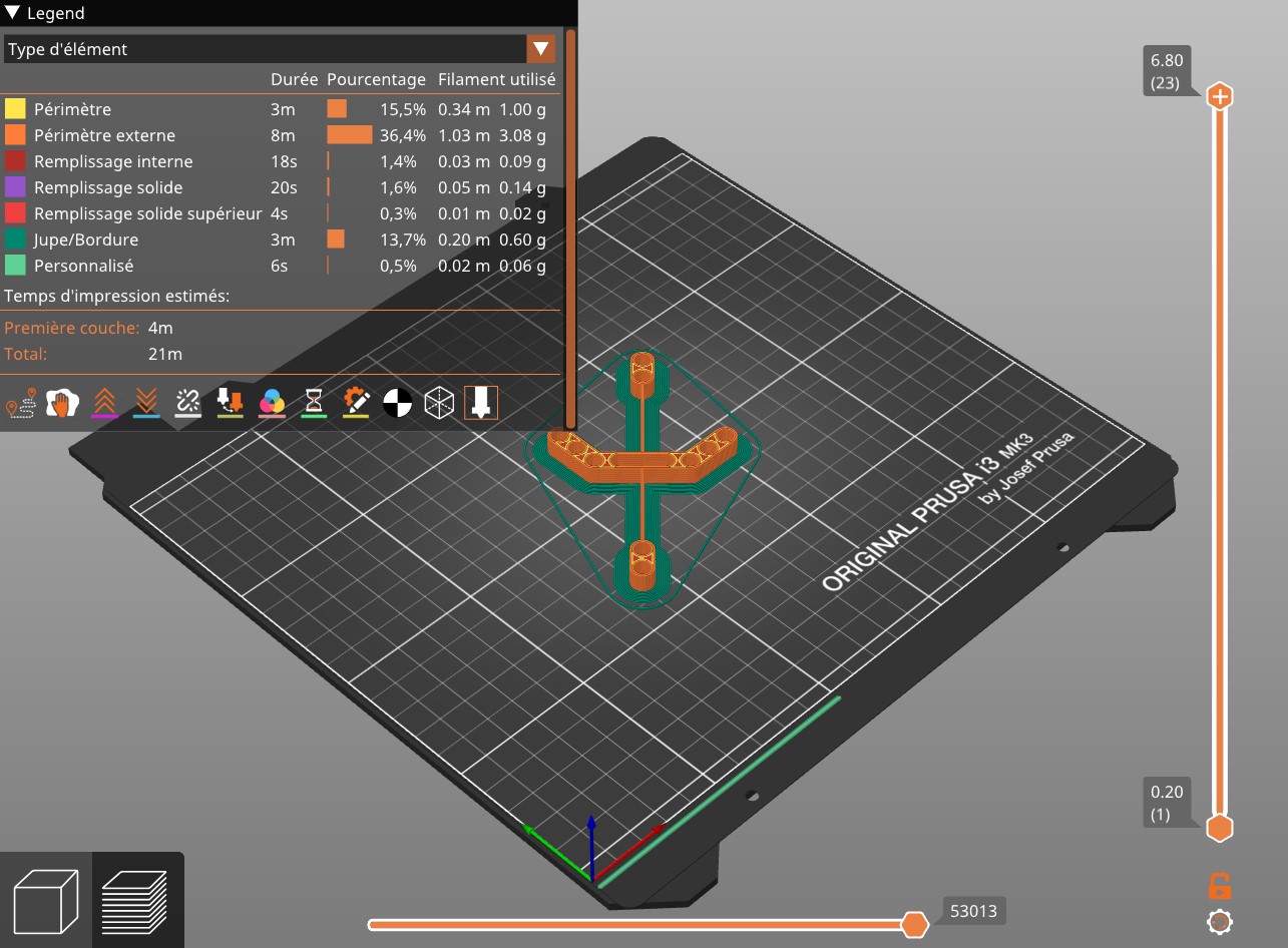
The vertical bar on the right allows to choose the layers you want to preview. The horizontal bar at the bottom allows to travel through a simulation of the selected layer’s printing process.
Let’s zoom a bit in order to understand the different colors :
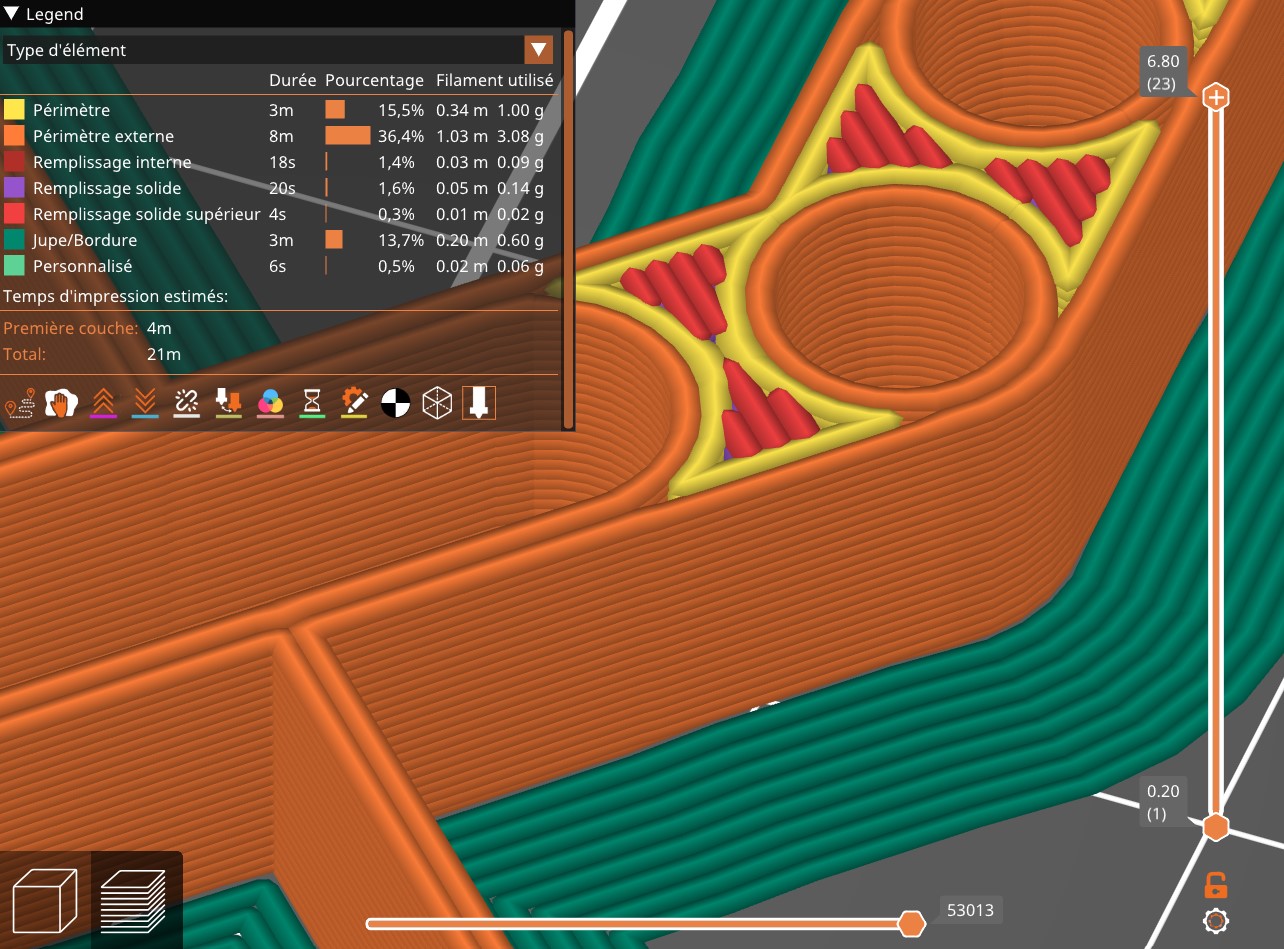
- Orange and yellow correspond to the perimeter of the model.
- Red and purple correspond to the filling inside the perimeter.
- Dark green is the border.
The border increases the stability of the object while it is being printed. It was not really necessary for this model but it allows to illustrate this feature.
Notice that you can also see the printing time which, there, would be 21 minutes.
Let’s get back in the printing settings window. If you modify any setting, you will have to select Cut now again in order to preview the printing process. Select the Supports setting and select something else than None then select again Cut now. If your object is as flat as mine, you should not see any changes. In order to understand what Supports do, let’s modify a bit our object’s orientation :
Let’s now select Supports, On the board only and Cut now. The supports are now visible in green and their usefulness is now quite obvious. It simply allows the object to be stable during the printing process.
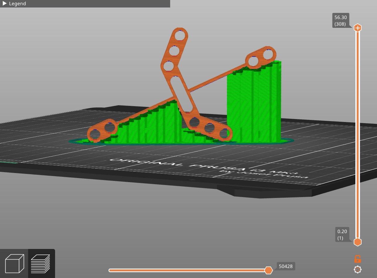
However, for our model, no supports are needed if we place the model correctly on the board.
Once your are pleased with the settings you selected, you can select Export G-code at the bottom of the printing setting window and PrusaSlicer will generate a code that the printer can understand.
3D printing#
Design analysis#
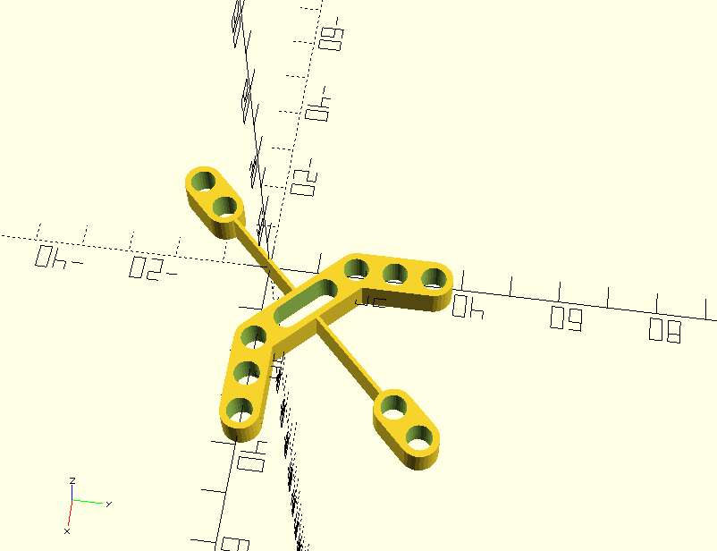
As shown in the previous section, my designed flexlink is the left picture bellow. Its working mechanism is represented on the right.
Let’s have a look back to its code :
// © 2019. This work is openly licensed via CC BY NC 4.0.

include <support_w_holes_v3.scad>
include <flexlink_1.scad>

//Holes parameters
//Lego circles radius : 2.4mm
rad_holes = 2.6 ;
n_holes = 3;

//Dimensions parameters
//Lego height : 9.6 mm
//Lego width : 8 mm
width = 8;
height = 9.6*0.7;
//Support length computation
length = 2*(width/2) + (n_holes-1)*8;

bond_length = 20;

//Holes parameters
n_holes_2 = 2;

//Bond parameters
bond_length_2 = 50;
bond_width = 0.8;


// Support
n_bond_length = bond_length+width/sqrt(2);

module bond(){
    difference(){

    //+
    translate([(n_bond_length)/sqrt(2)/2,n_bond_length/sqrt(2)/2,0])

    union(){

    rotate([0,0,-45])
    cube([n_bond_length,width,height],center=true);

    rotate([0,0,45])
    flexlink_1(n_holes_2, rad_holes, width, height, bond_length_2, bond_width);
    }

    //-
    translate([(n_bond_length)/sqrt(2)/2,n_bond_length/sqrt(2)/2,0])
    rotate([0,0,-45])

    union(){
    cube([n_bond_length-16,2*rad_holes,height+0.01],center=true);
    translate([(n_bond_length-16)/2,0,0])
    cylinder(height+0.01,rad_holes,rad_holes,center=true);
    translate([-(n_bond_length-16)/2,0,0])
    cylinder(height+0.01,rad_holes,rad_holes,center=true);
    }

    translate([bond_length/sqrt(2) + width/2,0,0])
    cylinder(height+0.01, rad_holes,rad_holes, center = true);

    translate([0,bond_length/sqrt(2) + width/2,0])
    cylinder(height+0.01, rad_holes,rad_holes, center = true);

}
}

union(){
//Bond
bond();
//Support w holes
translate([bond_length/sqrt(2)+length/2,0,0])
support_w_holes(n_holes, rad_holes, width, height);

translate([0,bond_length/sqrt(2)+length/2,0])
rotate([0,0,-90])
support_w_holes(n_holes, rad_holes, width, height);
}
One can identify the following parameters :
rad_holes: the radii of all the holesn_holes: the number of holes of the central partwidth: the width of the central partheight: the height of the whole piecebond_length: the length of the central partn_holes_2: the number of holes on the edges of the stembond_length_2: the stem lengthbond_width: the width of the stem
I wanted my design to be fixable on Legos. Let’s have a reminder of the important Lego’s dimensions :
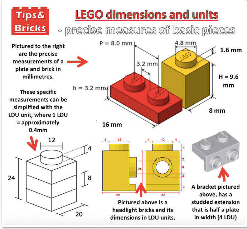
The upper part has a 2.4 mm radius and the height of a normal piece is 9.6 mm. This is the reason why I chose the radii of my design’s holes to be 2.6 mm, they have to be a bit larger than the Lego’s upper part in order to be fixed on the latter. Then I chose my design’s height to be 70% of the Lego’s height, for aesthetic reasons.
Cleaning and security#
Before starting using the 3D printer, be sure that the printing board is clean. You can clean it with paper towel and some multi-purpose cleaner product.
The board will be heated during the process but its temperature is not dangerous.
In contrast, the nozzle of the printer will be really hot so do not touch it !
Transfering G-code and printing#
When the printer is ready, you can transfer your G-code on a SD card and insert it in the printer. With the printer controller, select your file and start the printing.
Manual post-processing#
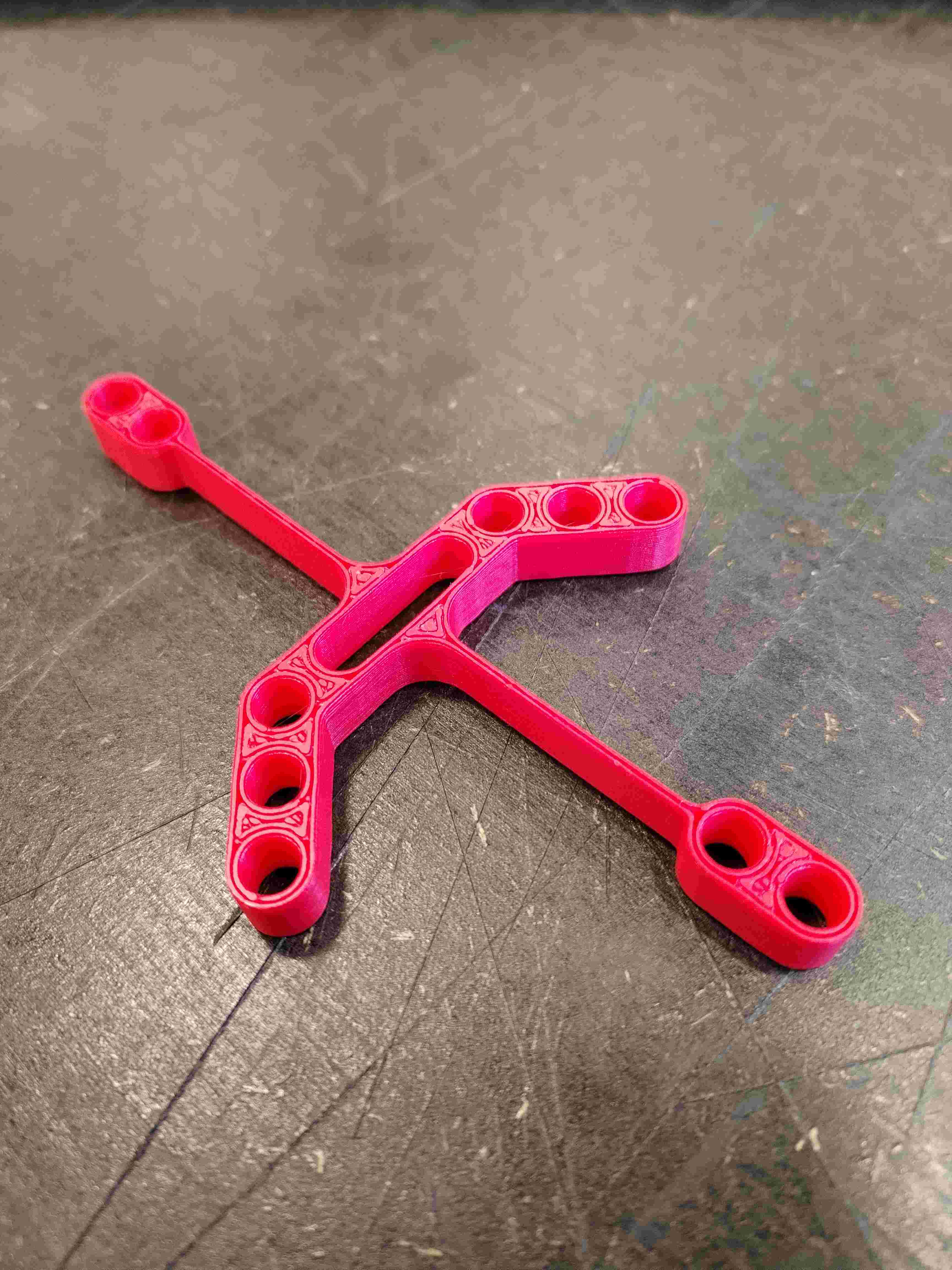
Once the printing is over, you will have to manually clean your object. Indeed, you have to remove the printed border and supports if there are any.
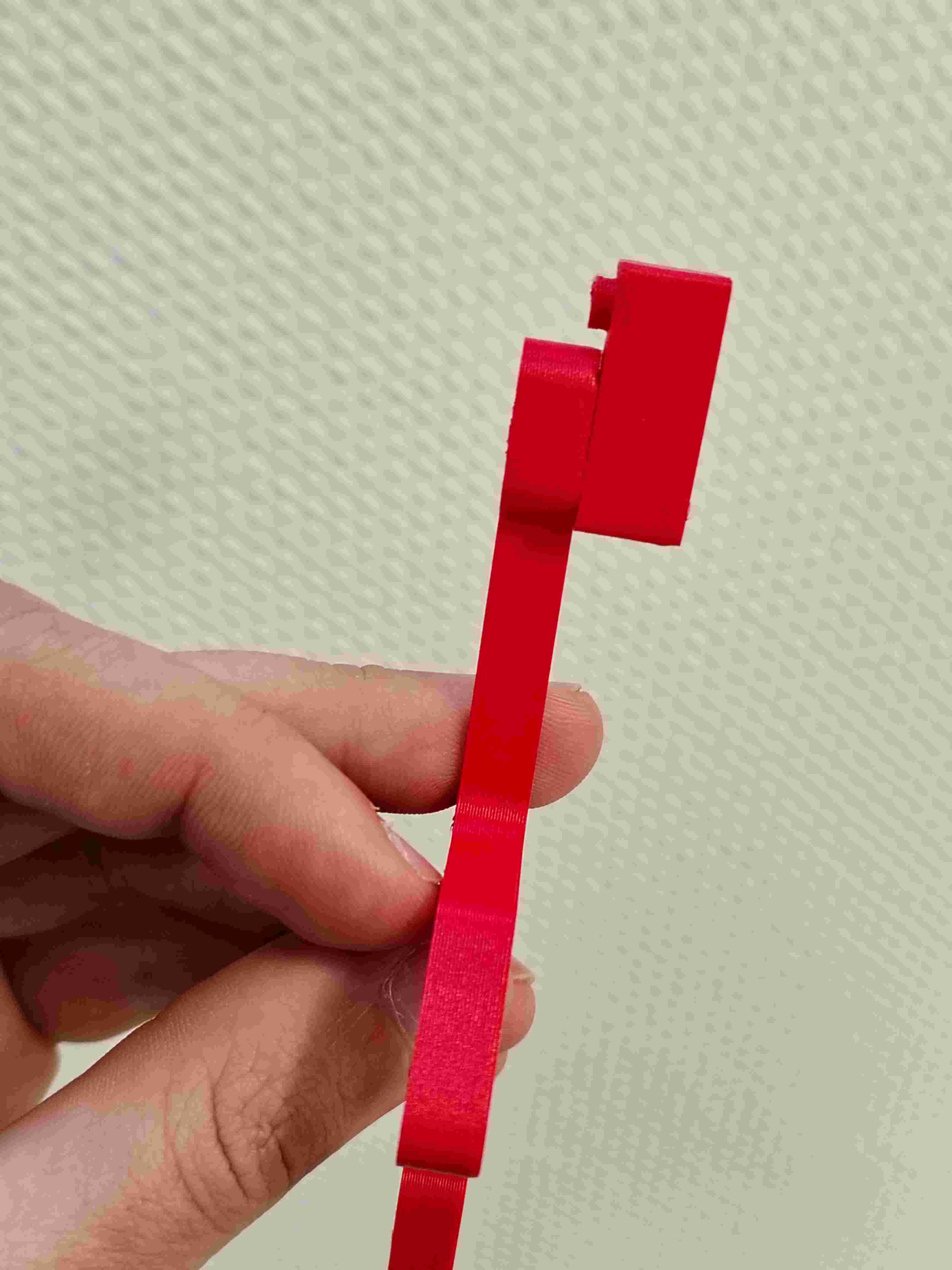
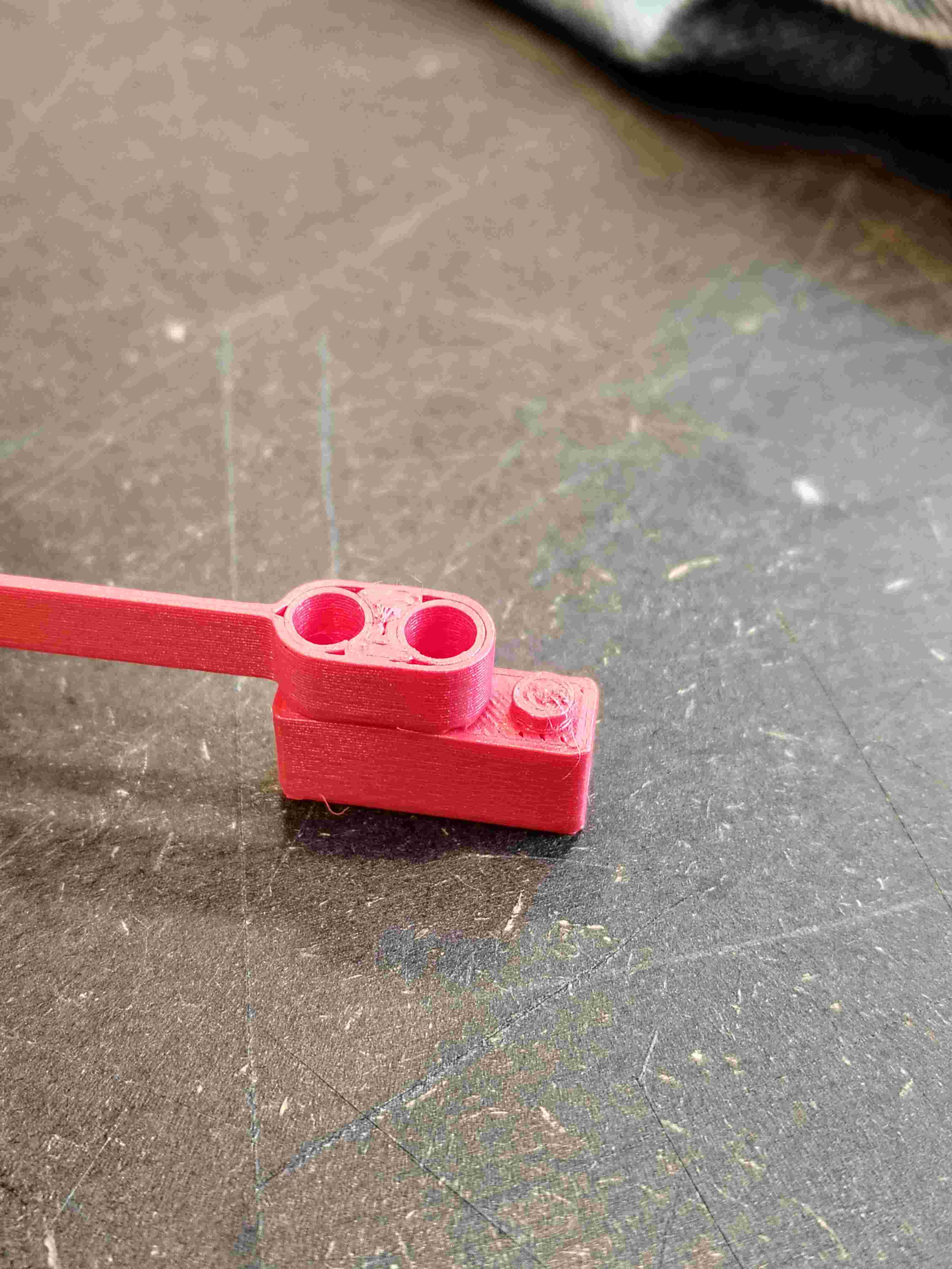
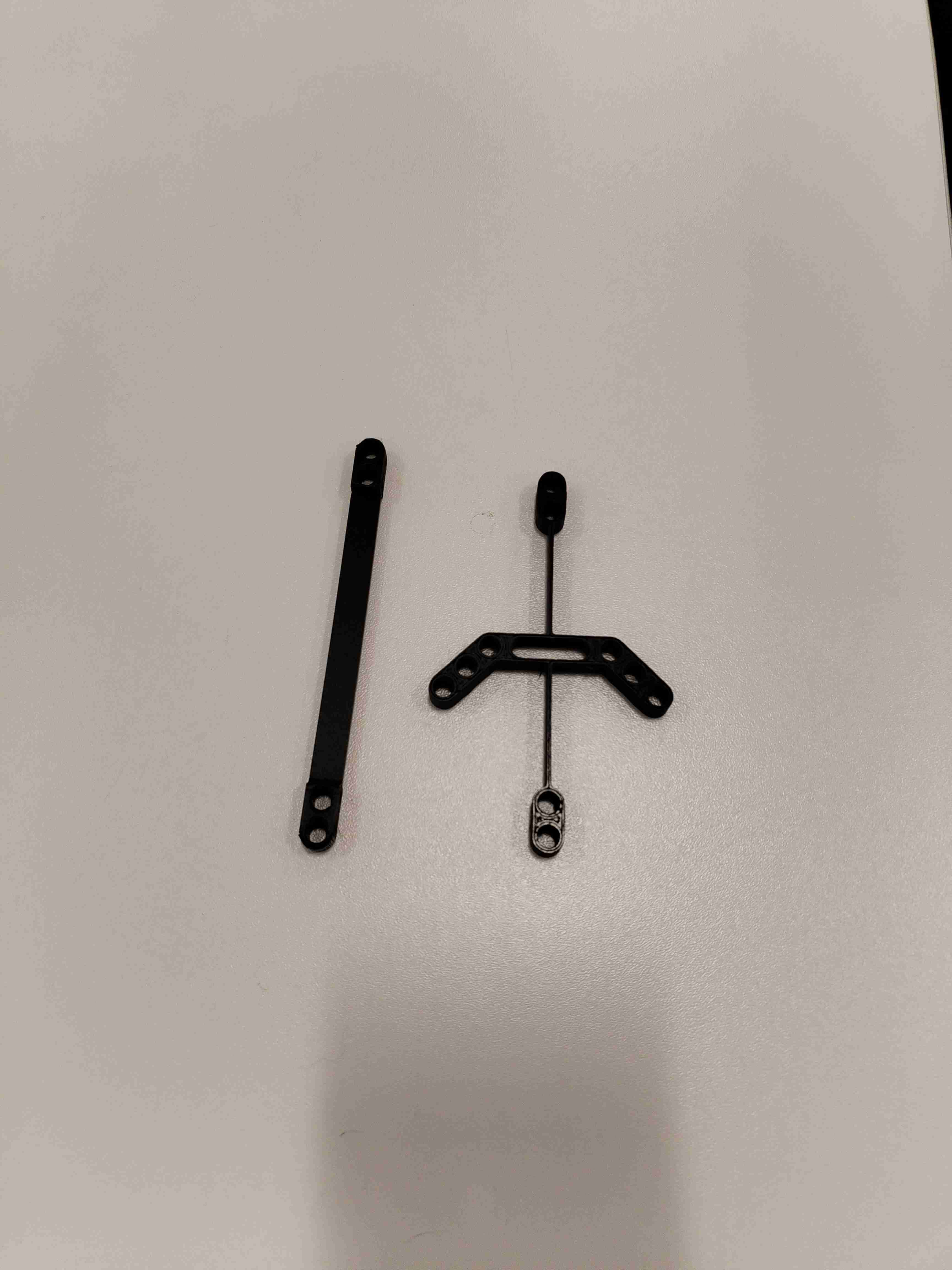
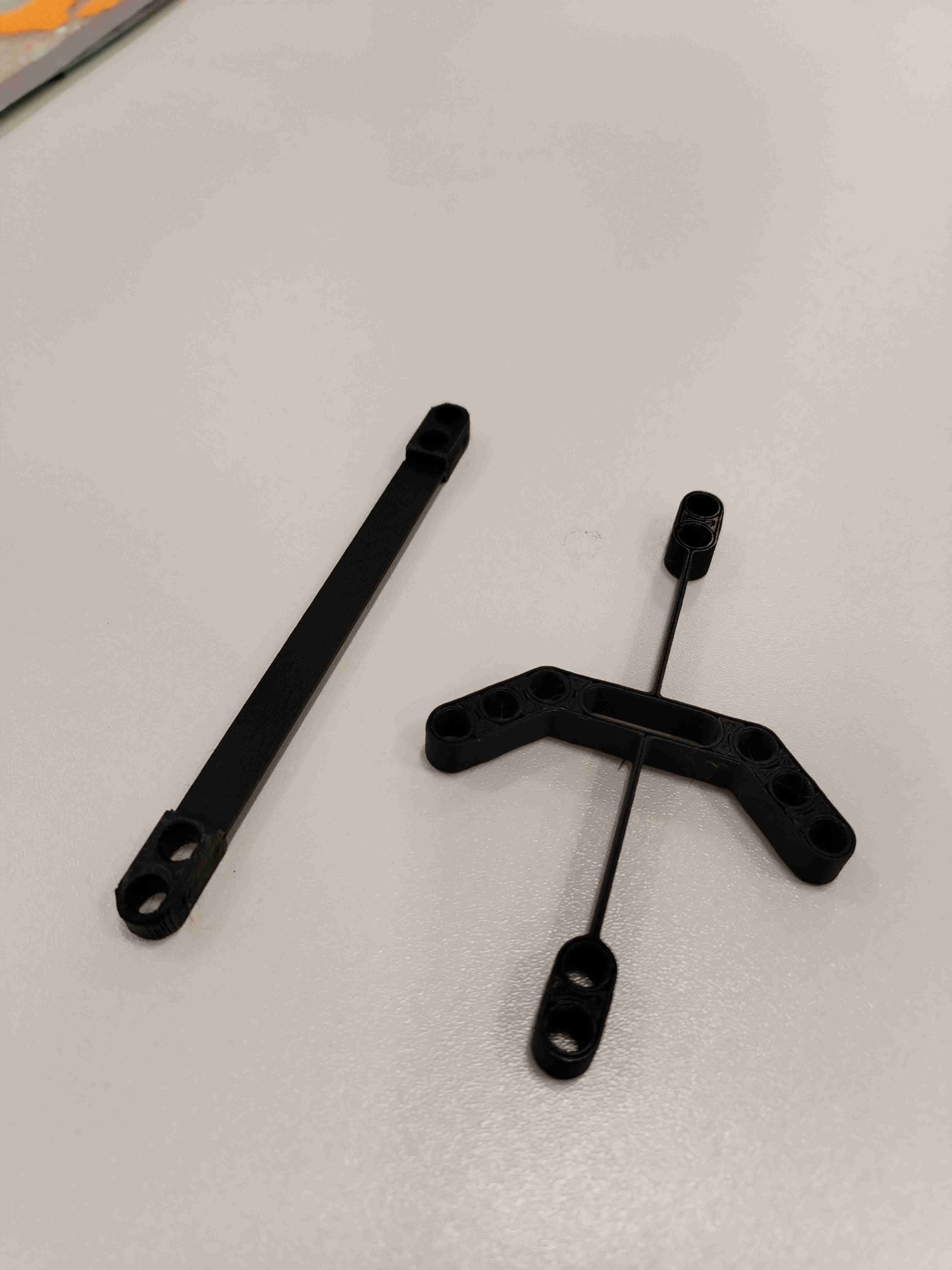
Here are two pictures of our clean printed objects :
Improvements#
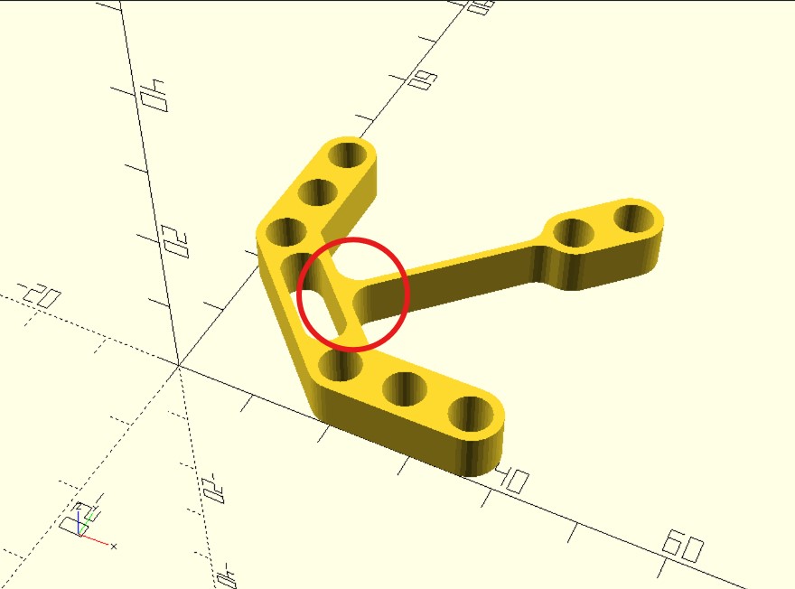
After playing a bit with our objects, one of them broke a bit :
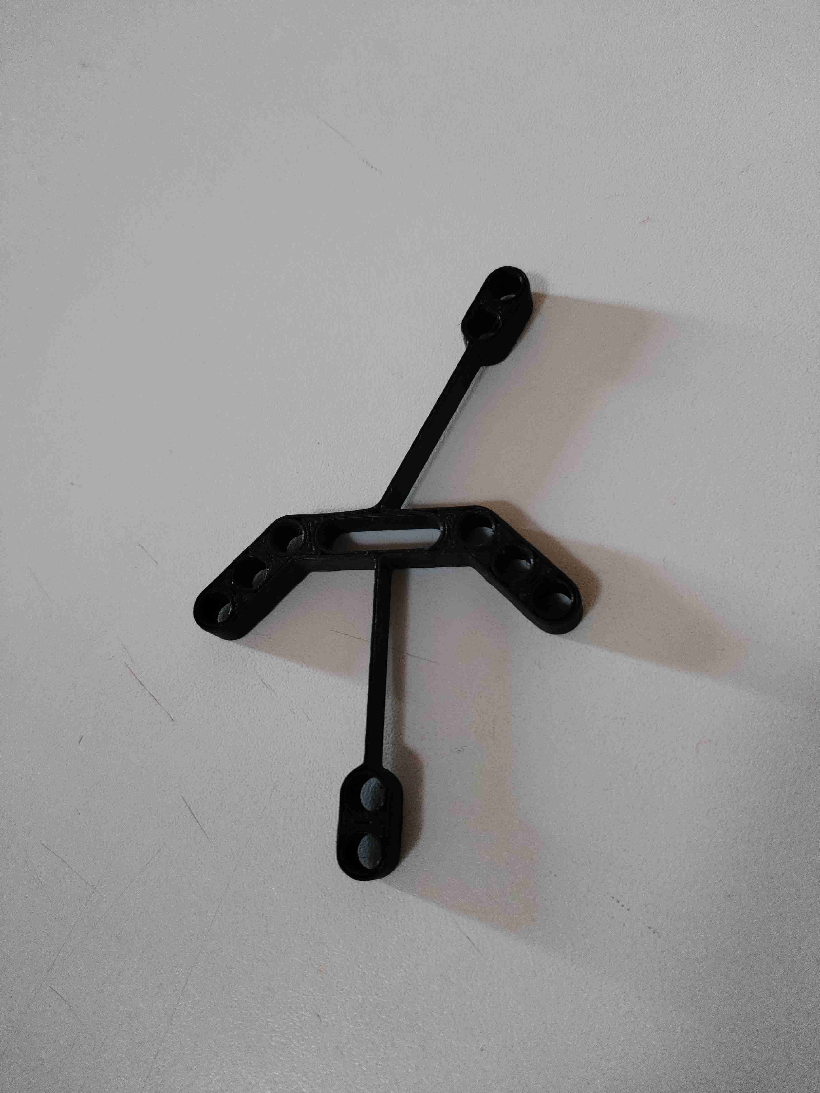
An improvement would be to do a smoother and hence stronger connection between the main structure and the branches as it can be seen on the model I took inspiration from. Here you can compare the two connections. My design is on the right and the inspiration is on the left.
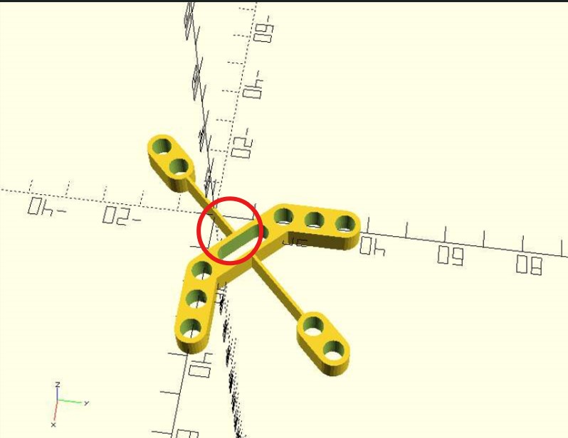
I then modified my design and printed a new and stronger version :
Lego fixation#
I finally printed a Lego piece to verify if my design could indeed be attached to it.
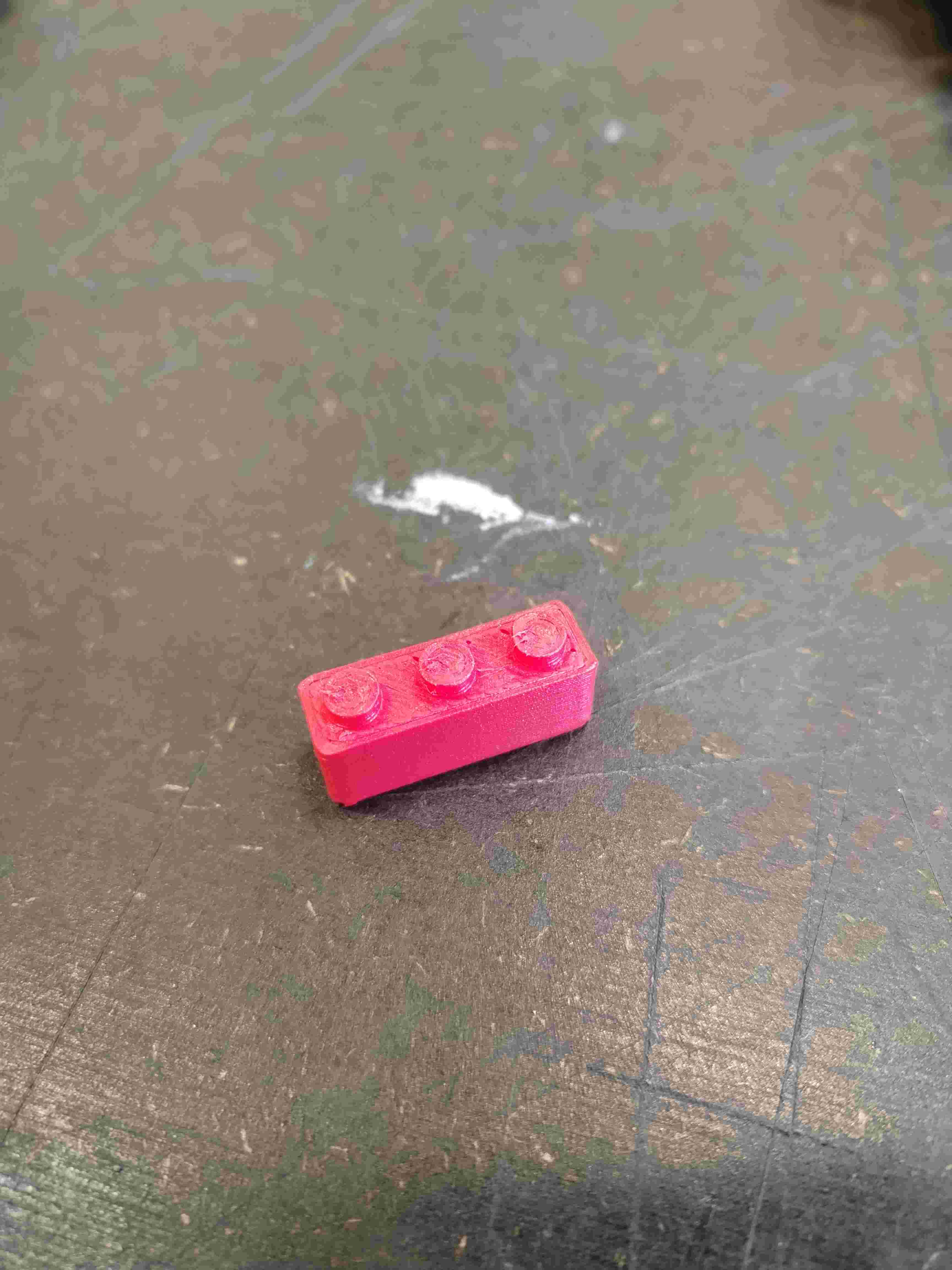
And it worked !