2. Computer Aided Design (CAD)#
This second module is dedicated to the documentation of the courses concerning “Computer Aided Design” or CAD. Indeed, in order to use digital fabrication machines it is first needed to understand the digital modeling.
Vectors pictures and Inkscape#
Vectors pictures are a different format of pictures than the usual pixel ones.

Pixel pictures are two times two tables where each entry contains three numbers defining a color. The image is then represented as a grid where each element, called a pixel, will be lighten with the color definied by the three numbers.
Vectors pictures are defined by a set of geometric elements (points, lines, curves, …) in a vector space. The properties of the geometric elements’ representations such as their color or the thickness of the lines are contained in the meta-data of the vector image so that a vector pictures software can then construct a pixel image on the screen of the user (because at the end, your screen only works with pixels).
If at the end, our screen displays pixel pictures anyway, why do we use vectors ? Well, the biggest advantages of vectors pictures are :
- Lower file size
- Easily customizable
- Environment adaptative
- Easily scriptable
The first advantage, for instance, is obvious when we think about the picture of a black line segment on a white background. A pixel picture must contain the information about the colour of each pixel of the pictures (all the black ones where the line passes and the white ones that constitue the background) while a vectors picture contains only the positions of the two extremal points, its colour, thickness and the colour of the background.
To generate vectors pictures, we learned how to use Inkscape. Tutorials can be found here.
3D design and OpenSCAD#
In order to freely use a 3D printer, it is essential to be able to design by ourselves our 3D models. We were introduced to two programs : OpenSCAD and FreeCAD however I will use OpenSCAD since I am feeling more confident about manipulating mathematical formulas and algorithms than a graphical interface I’m not familiar with. This section constitutes an overview of the OpenSCAD basics and how I used the software for this course. If you are intersted in learning OpenSCAD I highly recommend their tutorials which are really well done.
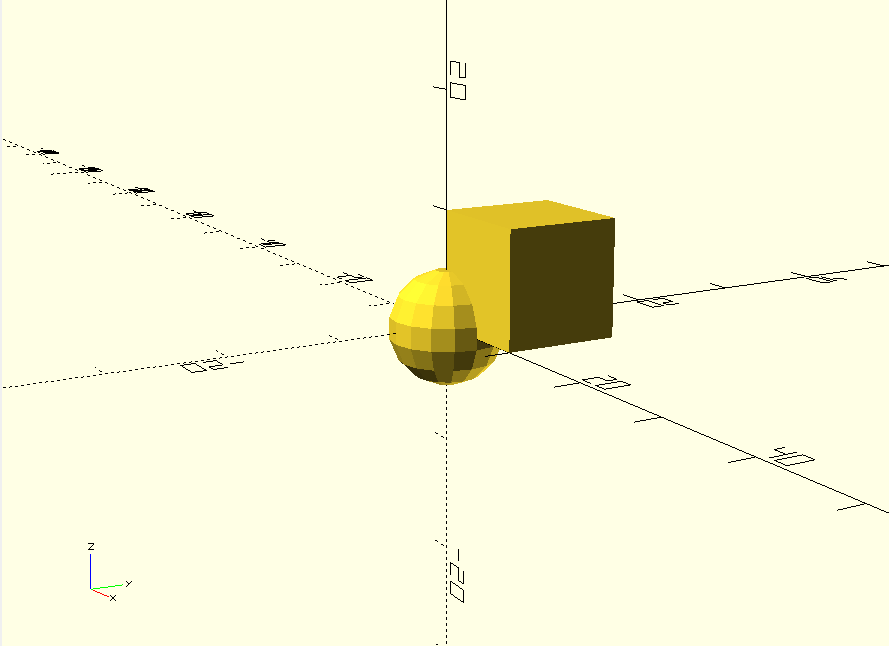
OpenSCAD allows us to design 3D models by coding and applying mathematical formulas to elementary objects such as cubes, spheres, etc.
For instance, the following code lines :
render as :
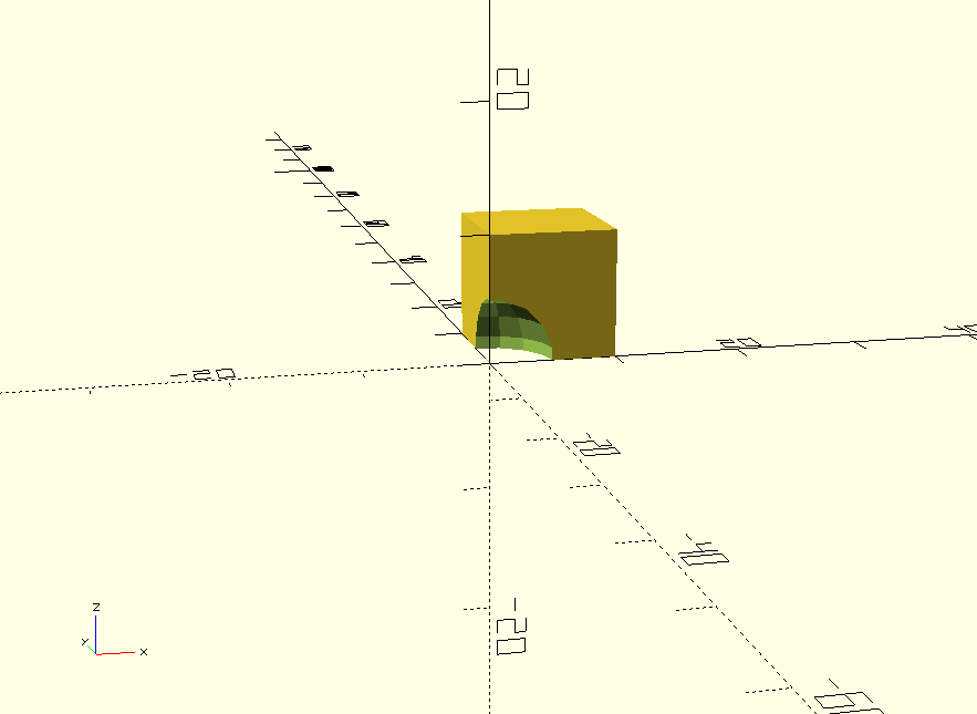
A lot of built-in functions allow to manipulate these kind of geometric elements. For instance the function difference() substract a 3D model from another :
render as :
It is also possible to modify the parameters of the geometric elements. For instance, the radius of the sphere or its resolution. Here, I show the renders of two spheres with different resolutions.
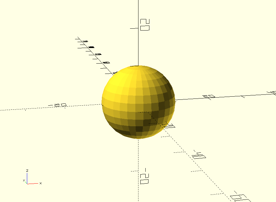

Notice that the resolution parameter is written $fn. We could also define it globally at the beginning of the script and it would then apply to all of the elements whose resolution is not specified. It is important to set a low resolution while designing your model to allow fast rendering. The resolution can then be increased once you want to execute the final rendering.
The main built-in functions of OpenSCAD can be found on their CheatSheet.
Importing files can be done using the function import(). For instance :
FlexLinks construction design#
Although we can import any open source design, it is essential that we learn how to design a 3D model by ourselves. I will describe in this section how I designed my first FlexLinks construction using OpenSCAD.
First prototype#
By checking the FlexLinks constructions, I noticed that a common structure of all the constructions is a roundish support with holes that allow to fix the design to Legos. My first goal is thus to design such a simple support using OpenSCAD.
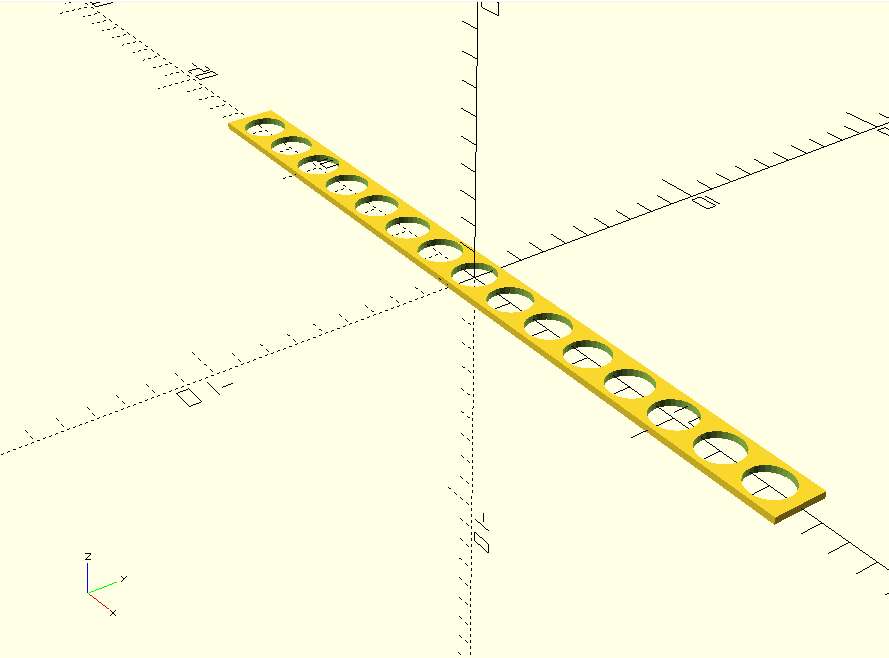
I started by generating a parallepiped with a certain number of holes. I defined a module hole() that generates a cylinder corresponding to the hole and I used a for loop in a difference() function to make the number of holes parametrizable.
The code is :
$fn = 30;

rad_holes = 0.8;
space_holes = rad_holes/2;

n_holes = 15;

length = n_holes*(space_holes+ 2*rad_holes) + space_holes;
width = (2*rad_holes)/0.8;
height = 0.25;

module hole(){
    cylinder(height+0.001,width*0.8/2, width*0.8/2, center=true);
    }

difference(){
cube([length,width,height], center = true);
border = [-length/2-rad_holes,0,0];
for (i = [0:n_holes]){
    translate(border + (i+1)*[space_holes + 2*rad_holes,0,0])
    hole();
}
}
and it renders as :
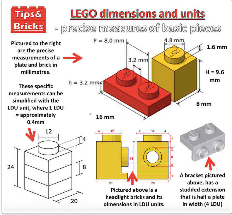
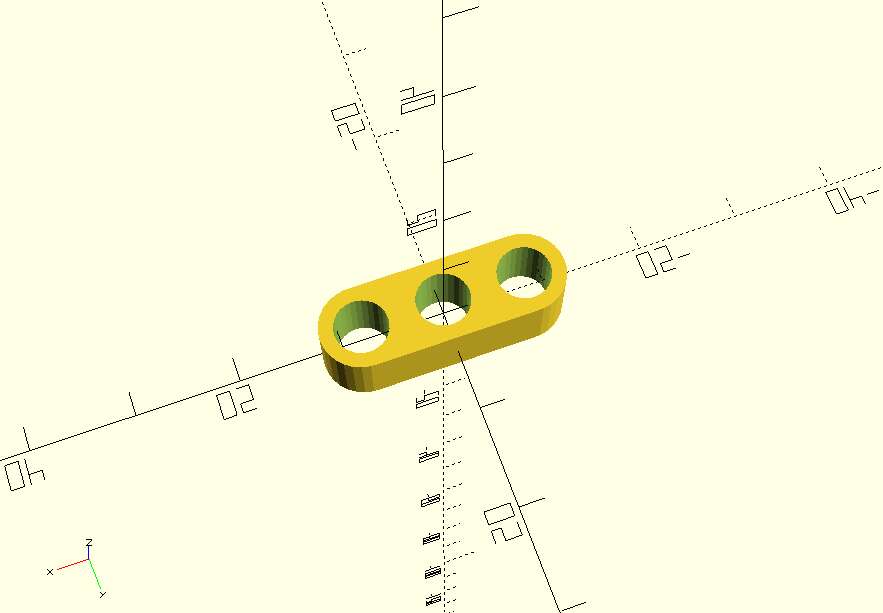
Next I wanted to make the edges of the structure roundish. I achieved this by making the parallepiped a bit shorter and then adding some cylinders at the edges. I also wanted implement the dimensions that would allow me to attach the model to Legos. I changed a bit the dimensions and made them easily parametrable.
The Legos dimensions are indicated on the following picture which I found on Simone’s website (who found it on Tips&Bricks), a former FabZero student.
The code is :
$fn = 30;

module hole(height, rad_holes){
    cylinder(height+0.001,rad_holes, rad_holes, center=true);
    }

module support(n_holes,rad_holes,width,height){

    center_to_center = 8;
    space_holes = center_to_center - 2*rad_holes;

    length = n_holes*(space_holes+ 2*rad_holes) + space_holes;

    cube_length = length-2*(space_holes+rad_holes);

    cube([cube_length,width,height], center = true);
    translate([cube_length/2,0,0])
    cylinder(height,width/2,width/2,center=true);
    translate([-(cube_length/2),0,0])
    cylinder(height,width/2,width/2,center=true);
}

module support_w_holes(n_holes,rad_holes, width, height){

    center_to_center = 8;
    space_holes = center_to_center - 2*rad_holes;

    length = n_holes*(space_holes+ 2*rad_holes) + space_holes;

    cube_length = length-2*(space_holes+rad_holes);

    difference(){
    support(n_holes, rad_holes, width, height);
    border = [-cube_length/2,0,0];
    for (i = [0:n_holes]){
        translate(border + i*[space_holes + 2*rad_holes,0,0])
    hole(height, rad_holes);
    }
    }
}
and renders as :
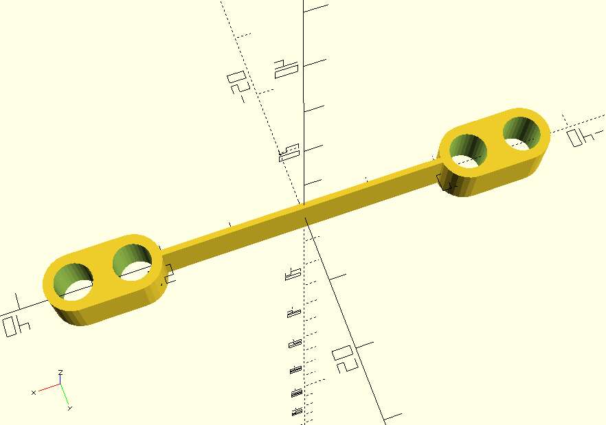
Finally, I created a new file in which I imported this structure’s module. I then generated two of them and added a bond between them. The code is :
include <support_w_holes_v2.scad>

//Holes parameters
//Lego circles radius : 2.4mm
rad_holes = 2.6;
n_holes = 2;

//Dimensions parameters
//Lego height : 9.6 mm
//Lego width : 8 mm
width = 8;
height = 9.6*0.7;
//Support length computation
length = 2*(width/2) + (n_holes-1)*8;

//Bond parameters
bond_length = 40;
bond_width = 0.8;

//Structure construction
union(){
    cube([bond_length+0.1, bond_width, height],center =true);

    translate([bond_length/2 + length/2,0,0])
    support_w_holes(n_holes, rad_holes, width, height);

    translate([-(bond_length/2 + length/2),0,0])
    support_w_holes(n_holes, rad_holes, width, height);
}
and renders as :
Second prototype#
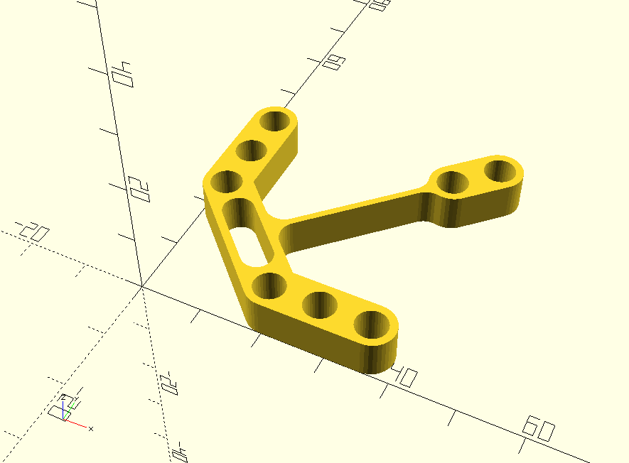
Now that I have the simple common structure. I will try to model a more complex shape. The goal was to model a parametric 3D shape that reproduces the following for certain parameters :
The code is :
// © 2019. This work is openly licensed via CC BY NC 4.0.

include <support_w_holes_v3.scad>
include <flexlink_1.scad>

//Holes parameters
//Lego circles radius : 2.4mm
rad_holes = 2.6 ;
n_holes = 3;

//Dimensions parameters
//Lego height : 9.6 mm
//Lego width : 8 mm
width = 8;
height = 9.6*0.7;
//Support length computation
length = 2*(width/2) + (n_holes-1)*8;

bond_length = 20;

//Holes parameters
n_holes_2 = 2;

//Bond parameters
bond_length_2 = 50;
bond_width = 0.8;


// Support
n_bond_length = bond_length+width/sqrt(2);

module bond(){
    difference(){

    //+
    translate([(n_bond_length)/sqrt(2)/2,n_bond_length/sqrt(2)/2,0])

    union(){

    rotate([0,0,-45])
    cube([n_bond_length,width,height],center=true);

    rotate([0,0,45])
    flexlink_1(n_holes_2, rad_holes, width, height, bond_length_2, bond_width);
    }

    //-
    translate([(n_bond_length)/sqrt(2)/2,n_bond_length/sqrt(2)/2,0])
    rotate([0,0,-45])

    union(){
    cube([n_bond_length-16,2*rad_holes,height+0.01],center=true);
    translate([(n_bond_length-16)/2,0,0])
    cylinder(height+0.01,rad_holes,rad_holes,center=true);
    translate([-(n_bond_length-16)/2,0,0])
    cylinder(height+0.01,rad_holes,rad_holes,center=true);
    }

    translate([bond_length/sqrt(2) + width/2,0,0])
    cylinder(height+0.01, rad_holes,rad_holes, center = true);

    translate([0,bond_length/sqrt(2) + width/2,0])
    cylinder(height+0.01, rad_holes,rad_holes, center = true);

}
}

union(){
//Bond
bond();
//Support w holes
translate([bond_length/sqrt(2)+length/2,0,0])
support_w_holes(n_holes, rad_holes, width, height);

translate([0,bond_length/sqrt(2)+length/2,0])
rotate([0,0,-90])
support_w_holes(n_holes, rad_holes, width, height);
}
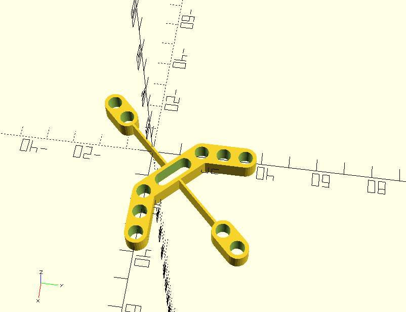
Here is an interactive 3D visualisation of the model. You can rotate the camera by click-and-dragging the mouse.
Next week, we will print our designs. I will work with Altay whose design is similar to my first prototype but with a different compliant rotation ax to increase the combinations of motion we could realize.